Panasonic PT-DW100U Dlp Projector - Multi Language - Page 32
Connecting signals to the, DVI-D input module
 |
View all Panasonic PT-DW100U manuals
Add to My Manuals
Save this manual to your list of manuals |
Page 32 highlights
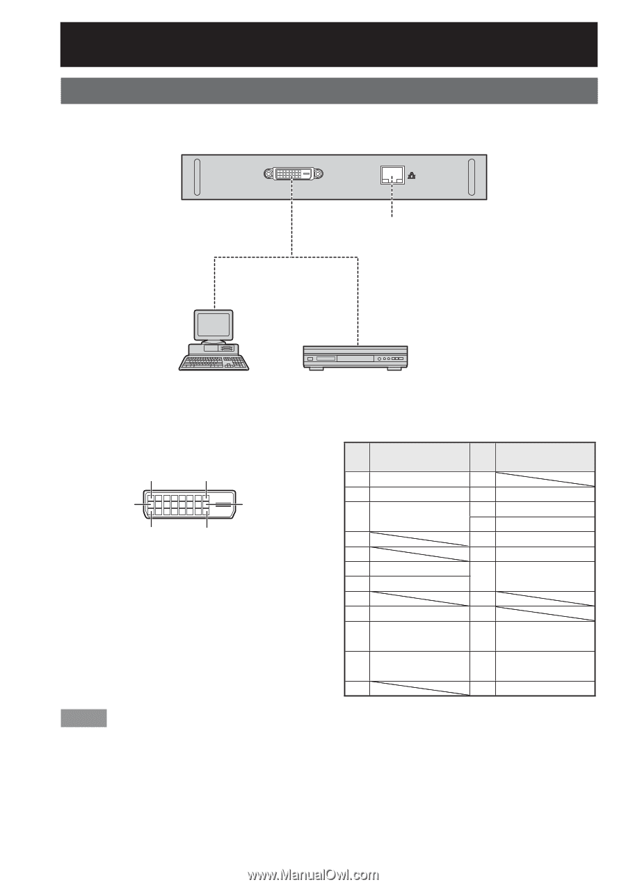
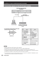
Installation of input module (optional) (continued) Connecting signals to the DVI-D input module DVI-D input module (optional) ET-MD77DV DVI Module ET-MD77DV DVI-D IN LAN DVI-D signal LAN terminal*1 (10BASE-T/100BASE-TX) PC with DVI output DVD player or high-vision video deck equipped with DVD/HDMI terminal • Pin assignments and signal names of DVI-D input terminal are listed in the table at right. # + - 4 5 = Outside view Pin No. Signal # T.M.D.S data 2- $ T.M.D.S data 2+ % T.M.D.S data 2/ 4 shield & ( ) DDC clock * DDC data + - T.M.D.S data 1- . T.M.D.S data 1+ / T.M.D.S data 1/ 3 shield 0 Pin No. Signal 1 2 +5V 3 Ground 4 Hot plug detection 5 T.M.D.S data 0- 6 T.M.D.S data 0+ 7 T.M.D.S data 0/ 5 shield 8 9 : T.M.D.S clock shield ; T.M.D.S clock+ = T.M.D.S clock- Note • The DVI-D signal input module supports only a single link. • The HDMI-DVI-D conversion cable is required to connect an HDMI-compliant device. • The EDID mode setting must be selected so that it corresponds to the device to be connected. (p. 72) • It is possible to connect the DVI-D input module with an HDMI- or DVI-D-compliant device, but with some devices the images may not appear or other problems may be encountered in operation. *1: The LAN terminal of the input module (optional) cannot be used with the PT-D10000U/PT-DW10000U. Use the LAN terminal that is provided as standard with the projector. 32 - ENGLISH
-
 1
1 -
2
-
3
-
4
-
5
-
6
-
7
-
8
-
9
-
10
-
11
-
12
-
13
-
14
-
15
-
16
-
17
-
18
-
19
-
20
-
21
-
22
-
23
-
24
-
25
-
26
-
 27
27 -
 28
28 -
 29
29 -
 30
30 -
 31
31 -
 32
32 -
 33
33 -
 34
34 -
 35
35 -
 36
36 -
 37
37 -
38
-
39
-
40
-
41
-
42
-
43
-
44
-
45
-
46
-
47
-
48
-
49
-
50
-
51
-
52
-
53
-
54
-
55
-
56
-
57
-
58
-
59
-
60
-
61
-
62
-
63
-
64
-
65
-
66
-
67
-
68
-
69
-
70
-
71
-
72
-
73
-
74
-
75
-
76
-
77
-
78
-
79
-
80
-
81
-
82
-
83
-
84
-
85
-
86
-
87
-
88
-
89
-
90
-
91
-
92
-
93
-
94
-
95
-
96
-
97
-
98
-
99
-
100
-
101
-
102
-
103
-
104
-
105
-
106
-
107
-
108
-
109
-
110
-
111
-
112
-
113
-
114
-
115
-
116
-
117
-
118
-
119
-
120
-
121
-
122
-
123
-
124
-
125
-
126
-
127
-
128
-
129
-
130
-
131
-
132
 |
 |