Panasonic PT-DW100U Dlp Projector - Multi Language - Page 62
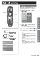
Adjusting the clamp, position, Edge blending adjustment, Press, to select, CLAMP, Press ENTER.
 |
View all Panasonic PT-DW100U manuals
Add to My Manuals
Save this manual to your list of manuals |
Page 62 highlights
How to use ADVANCED MENU (continued) Note • The abovementioned vertical stripes will not appear on the screen when all signals are input. • The picture may be distorted during the adjusting operation, but this is not a fault. • The input resolution can be adjusted only when RGB signal input is applied with RGB1 and RGB2 IN. Adjusting the clamp position Use the clamp position adjustment to achieve the optimal value when dark areas of the image are crushed or displayed in green. 1. Press ▲▼ to select "CLAMP POSITION". ADVANCED MENU DIGITAL CINEMA REALITY BLANKING INPUT RESOLUTION CLAMP POSITION EDGE BLENDING FRAME DELAY RASTER POSITION AUTO OFF DEFAULT Edge blending adjustment This projector has the function to hide the seams for multi-screens. 1. Press ▲▼ to select "EDGE BLENDING". ADVANCED MENU DIGITAL CINEMA REALITY BLANKING INPUT RESOLUTION CLAMP POSITION EDGE BLENDING FRAME DELAY RASTER POSITION AUTO OFF DEFAULT MENU SELECT CHANGE 2. Press ◄► to switch "EDGE BLENDING". • The setting will change as follows each time ◄► is pressed. OFF ON USER MENU SELECT ENTER SUB MENU 2. Press ENTER. • The "CLAMP POSITION" screen will be displayed. CLAMP POSITION POSITION ɹ1 MENU SELECT ADJUST 3. Press ◄► to adjust. • The value changes from 1 to 255. • The optimal value for the clamp position adjustment If dark areas are crushed: The optimal value is the point where the dark area is best improved. If the dark areas are displayed in green: The optimal value is the point where the green area becomes dark and clear. Note • The clamp position can be adjusted only when the RGB signal input is applied with RGB1 and RGB2 IN. 62 - ENGLISH • OFF: When the multi-screens are not going to be used. • ON: When the tilting inside the unit is to be used for the tilting of the edge blending area. • USER: When a specific tilting is to be used for the tilting of the edge blending area. (Separate software is required to establish these settings. Consult your dealer.) 3. Press ENTER. • The "EDGE BLENDING" screen will be displayed. EDGE BLENDING UPPER START OFF WIDTH LOWER START OFF WIDTH LEFT START OFF WIDTH RIGHT START OFF WIDTH MARKER BRIGHT ADJUST MENU SELECT ADJUST 0 128 0 128 0 128 0 128 OFF ENTER CHANGE
-
 1
1 -
2
-
3
-
4
-
5
-
6
-
7
-
8
-
9
-
10
-
11
-
12
-
13
-
14
-
15
-
16
-
17
-
18
-
19
-
20
-
21
-
22
-
23
-
24
-
25
-
26
-
27
-
28
-
29
-
30
-
31
-
32
-
33
-
34
-
35
-
36
-
37
-
38
-
39
-
40
-
41
-
42
-
43
-
44
-
45
-
46
-
47
-
48
-
49
-
50
-
51
-
52
-
53
-
54
-
55
-
56
-
 57
57 -
 58
58 -
 59
59 -
 60
60 -
 61
61 -
 62
62 -
 63
63 -
 64
64 -
 65
65 -
 66
66 -
 67
67 -
68
-
69
-
70
-
71
-
72
-
73
-
74
-
75
-
76
-
77
-
78
-
79
-
80
-
81
-
82
-
83
-
84
-
85
-
86
-
87
-
88
-
89
-
90
-
91
-
92
-
93
-
94
-
95
-
96
-
97
-
98
-
99
-
100
-
101
-
102
-
103
-
104
-
105
-
106
-
107
-
108
-
109
-
110
-
111
-
112
-
113
-
114
-
115
-
116
-
117
-
118
-
119
-
120
-
121
-
122
-
123
-
124
-
125
-
126
-
127
-
128
-
129
-
130
-
131
-
132
 |
 |
