Pioneer 1140HD Owner's Manual - Page 72
Watching an image from a computer
 |
UPC - 012562829593
View all Pioneer 1140HD manuals
Add to My Manuals
Save this manual to your list of manuals |
Page 72 highlights
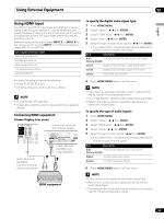
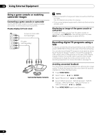
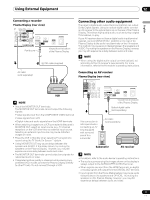
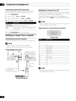
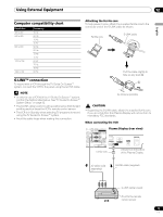
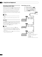
12 Using External Equipment Switching the optical audio signal type Set up for the DIGITAL AUDIO output terminal (OPTICAL), according to your AV receiver's operating instructions. 1 Press HOME MENU. 2 Select "Option". ( / then ENTER) 3 Select "Digital Audio Out". ( / then ENTER) 4 Select "Dolby Digital" or "PCM". ( / then ENTER) Item Description Dolby Digital Dolby Digital: outputs in the Dolby Digital format (factory default) PCM: outputs in the PCM format PCM Always outputs in the PCM format regardless of the types of signals 5 Press HOME MENU again to exit the menu. Watching an image from a computer Connecting a personal computer Use the PC terminals to connect a personal computer (PC). NOTE • The PC input terminals are DDC2B-compatible. • Ability to use Plug & Play depends on the computer. Plasma Display (rear view) Viewed from the bottom of the Plasma Display AV cable with a mini plug (sold separately) (for PC audio connection) RGB cable (sold separately) Displaying an image from a PC When connected to a PC, the input signal type is automatically identified. If the image from the PC does not come in clearly, you may need to use Auto Setup. See page 64. To watch an image coming from the PC, press PC on the remote control or press INPUT on the Plasma Display to select "PC". NOTE • The PC terminals are for PC use only. Do not connect audio/ visual equipment to PC terminals. Signal names for 15-pin mini D-sub connector Pin No. 1 2 3 4 5 6 7 8 9 10 11 12 13 14 15 543 21 10 9 8 7 6 15 14 13 12 11 (front view) Signal name R G B Not connected Not connected GND (ground) GND (ground) GND (ground) +5V GND (ground) Not connected SDA HD VD SCL NOTE • An Apple® Macintosh® adaptor may be required for use with some Macintosh computers. Personal Computer 72 En
-
 1
1 -
2
-
3
-
4
-
5
-
6
-
7
-
8
-
9
-
10
-
11
-
12
-
13
-
14
-
15
-
16
-
17
-
18
-
19
-
20
-
21
-
22
-
23
-
24
-
25
-
26
-
27
-
28
-
29
-
30
-
31
-
32
-
33
-
34
-
35
-
36
-
37
-
38
-
39
-
40
-
41
-
42
-
43
-
44
-
45
-
46
-
47
-
48
-
49
-
50
-
51
-
52
-
53
-
54
-
55
-
56
-
57
-
58
-
59
-
60
-
61
-
62
-
63
-
64
-
65
-
66
-
 67
67 -
 68
68 -
 69
69 -
 70
70 -
 71
71 -
 72
72 -
 73
73 -
 74
74 -
 75
75 -
 76
76 -
 77
77 -
78
-
79
-
80
-
81
-
82
-
83
-
84
-
85
-
86
-
87
-
88
-
89
-
90
-
91
-
92
-
93
-
94
-
95
-
96
-
97
-
98
-
99
-
100
-
101
-
102
-
103
-
104
-
105
-
106
-
107
-
108
-
109
-
110
-
111
-
112
-
113
-
114
-
115
-
116
-
117
-
118
-
119
-
120
 |
 |
