Ridgid MS255SR Operation Manual
Ridgid MS255SR Manual
 |
View all Ridgid MS255SR manuals
Add to My Manuals
Save this manual to your list of manuals |
Ridgid MS255SR manual content summary:
- Ridgid MS255SR | Operation Manual - Page 1
OPERATOR'S MANUAL 10 INCH SLIDING COMPOUND MITER SAW WITH DUAL LASER MS255SR � WARNING: To reduce the risk of injury, the user must read and understand the operator's manual before using this product. Thank you for buying a RIDGID product. 1-866-974-3443/USA SAVE THIS MANUAL FOR FUTURE REFERENCE - Ridgid MS255SR | Operation Manual - Page 2
General Safety Instructions 2 Specific Safety Instructions 3 Additional Instructions for Safe Operation 4 Symbols 5 Electrical 6 Lasers 7 Glossary 7 Features 8 Tools Needed 11 Loose Parts 11 Assembly 12 Adjustments 13 Operation 18 Maintenance 31 Troubleshooting 33 Warranty 34 - Ridgid MS255SR | Operation Manual - Page 3
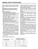
this miter saw and how to use it safely. � WARNING: Read and understand all instructions. Failure to follow all instructions listed below may result in electric shock, fire and/or serious personal injury. READ ALL INSTRUCTIONS • Keep guards in place and in working order. • Remove adjusting keys - Ridgid MS255SR | Operation Manual - Page 4
before changing the blade or servicing the saw. • Do not expose to rain or use in a damp location. • When servicing, use only identical replacement parts. • Never reach around the saw blade. • Do not perform any operation freehand. Always place the work piece to be cut on the miter saw table - Ridgid MS255SR | Operation Manual - Page 5
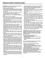
Read the Operator's Manual carefully. Learn safety equipment that the operator of the saw wears. • Inspect the operation. A guard or other part that is damaged should be properly repaired or replaced by a qualified person. • Save these instructions. Refer to them frequently and use them to instruct - Ridgid MS255SR | Operation Manual - Page 6
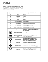
minute Wet conditions alert Do not expose to rain or use in damp locations. Read the operator's manual Eye protection To reduce the risk of injury, user must read and understand operator's manual before using this product. Always wear safety goggles or safety glasses with side shields and a full - Ridgid MS255SR | Operation Manual - Page 7
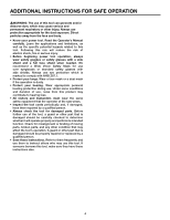
only identical replacement parts. � WARNING: To avoid serious personal injury, do not attempt to use this product until you read thoroughly and understand completely the operator's manual. Save this operator's manual and review it frequently for continuing safe operation and instructing others who - Ridgid MS255SR | Operation Manual - Page 8
a qualified service technician. • Do not attempt to repair the laser guide by yourself. • Do not attempt to change any parts of the laser guide. operator's glossary of terms • Bevel Cut: A cutting operation made with the blade at any angle other than 90° to the miter table. • Blade Flange: A ring - Ridgid MS255SR | Operation Manual - Page 9
making a slide cut. • Spindle Lock: Allows the user to stop the blade from rotating while tightening or loosening the blade screw during blade replacement or removal. • Spindle: The revolving shaft on which a blade or cutting tool is mounted. • Throat Plate: A plate inserted in the Miter Saw's table - Ridgid MS255SR | Operation Manual - Page 10
Lock-off button Laser light adjustment screw Spindle-lock button Miter angle indicator Miter-lock lever Bevel-lock lever Depth stop adjustment bolt Crown molding stop button Bevel scale Locking pin Bevel 33.9° (for USA)/ 30° (for Canada) stop block Upper sliding fence Blade wrench storage Fig - Ridgid MS255SR | Operation Manual - Page 11
lever To lock the saw at desired bevel angles. wrenches The larger blade wrench is used for changing the blade. One end of the blade wrench is a Phillips screwdriver and the other end is a hex key. The smaller hex key is used for laser adjustment and for miter 0° fine adjustment. The storage area - Ridgid MS255SR | Operation Manual - Page 12
Loose parts The following items are included with your sliding compound miter saw: • Dust Bag • Blade wrench • Hex key • Work piece clamp • Operator's manual Blade wrench Combination square 3/8" Open-end wrench Fig. 3 OPERATOR'S MANUAL 10 INCH SLIDING COMPOUND MITER SAW WITH DUAL LASER MS255SR - Ridgid MS255SR | Operation Manual - Page 13
checking for interference between the blade and the miter fence. Damage could result to the blade if it strikes the miter fence during operation of the saw. � WARNING: Always make sure that the compound miter saw is securely mounted to a workbench or an approved work stand. Failure to heed this - Ridgid MS255SR | Operation Manual - Page 14
the hex-head bolts. 7. Replace the upper sliding fences and reattach the fence-locking knobs. NOTE: If the saw has not been used recently, verify that the blade is square to the fence, and readjust if necessary. MITER-ANGLE INDICATOR ADJUSTMENT Fig. 8 1. Unplug the saw. � WARNING: Failure to - Ridgid MS255SR | Operation Manual - Page 15
is pointing to 0° on the bevel scale. 4. If the indicator is not pointing to 0°, loosen the bevel-angle indicator screw, adjust the indicator to 0° on bevel-angle scale, and then retighten the screw. Blade 90° square to miter table Bevel-lock lever Fig. 9 Fig. 10 Inner screw Fig. 11 Fig - Ridgid MS255SR | Operation Manual - Page 16
adjustments ADJUSTING THE BLADE TO THE MITER TABLE 45° BEVEL, 0° MITER Fig. 13-15 1. Unplug the saw. � WARNING: Failure to unplug your saw could result in accidental starting causing serious injury. 2. Lift the bevel-lock lever to release the bevel-lock. 3. Set the bevel-angle indicator to 45°. - Ridgid MS255SR | Operation Manual - Page 17
-Lock Lever Adjustment Fig. 16a - 16b The bevel-lock lever securely locks your compound miter saw at the desired bevel angles. Press the lever down to lock the head assembly. The bevel-lock lever can be adjusted, if necessary. 1. Unplug the saw. � WARNING: Failure to unplug your saw could result - Ridgid MS255SR | Operation Manual - Page 18
in the pivot joints, have your saw serviced by a qualified service technician before using. 48° and 45° stop plate Fig. 18a Pull out the left stop plate (rear view), to turn the saw from the bevel 45° left to bevel 48° left. Bevel 45° left Adjust the left stop plate Bevel 48° left Pull out the - Ridgid MS255SR | Operation Manual - Page 19
is tight or if there is play in the bevel pivot, have your saw serviced by a qualified service person before using. Laser light adjustment NOTE: Avoid direct eye exposure when using the laser light. 1. Set both the bevel angle and the miter table at 0°. 2. Use the work piece clamp or a C-clamp - Ridgid MS255SR | Operation Manual - Page 20
provided or a C-clamp (sold separately). The work piece clamp angle is adjustable in both horizontal and vertical axes. Horizontal adjustment: The work piece clamp can adjust left 90° to right 90° (Fig. 19b). Vertical adjustment: the work piece clamp has multiple quick stops for cutting base molding - Ridgid MS255SR | Operation Manual - Page 21
knob on the upper sliding fences to adjust them. The lower fences can be moved to either of two positions. When making a crosscut or a miter cut, move the lower fence closer to the blade to better support the work piece. When making a bevel cut, move the lower fence away from the blade to make sure - Ridgid MS255SR | Operation Manual - Page 22
operator, and the saw arm is lowered to the work piece and then pushed to the rear of the saw to make the cut. � WARNING: Never pull the saw toward you during a cut. The blade can suddenly climb up on top of the work piece and force itself toward you. Follow these instructions for making your slide - Ridgid MS255SR | Operation Manual - Page 23
at the end of the cut and jam the blade (see CUTTING WARPED MATERIAL, page 25). 10. Turn on the laser and align the pencil line in between the dual laser lines. 11. Use the work piece clamp to secure the work piece against the saw table and fence. Fig. 24 Fig. 25 12. When cutting a long - Ridgid MS255SR | Operation Manual - Page 24
). Fig. 26 9. Turn on the laser, and align the pencil line between the dual laser lines. 10. Use the work piece clamp to secure the work piece against the miter saw table and fence. 11. When cutting a long work piece, use a 3.5" block (not supplied) to support the long work piece. � CAUTION: Never - Ridgid MS255SR | Operation Manual - Page 25
OPERATION Adjusting the Bevel-Lock Lever (Fig. 27a-27b) The bevel-lock lever securely locks your compound miter saw at the desired bevel angles. Press the lever down to lock the saw arm. The bevel-lock lever can be adjusted, if necessary. 1. Unplug the saw. � WARNING: Failure to unplug your saw - Ridgid MS255SR | Operation Manual - Page 26
cut and jam the blade. 11. Turn on the laser and align the pencil line between the dual laser lines. 12. Use the work piece clamp to secure the work piece against the saw table and fence. 13. When cutting a long work piece, use a 3.5" block (not supplied) to support the long work piece. � CAUTION - Ridgid MS255SR | Operation Manual - Page 27
OPERATION GROOVES Fig. 29-30 The depth-stop adjustment is a feature used when cutting grooves in the work piece. The depth stop adjustment is used to limit the blade depth. A groove should be cut as a slide cut. 1. Unplug the saw. � WARNING: Failure to unplug the saw could result in accidental - Ridgid MS255SR | Operation Manual - Page 28
dual laser lines. 5. Use extra support when cutting long work pieces. 6. Carefully follow all instructions for applicable miter, bevel or compound cuts. Molding lying flat on miter table (before clamping) Miter at 0° Fence Miter saw Molding standing up against fence (before clamping) Fence - Ridgid MS255SR | Operation Manual - Page 29
and the fence. NOTE: The advantage to cutting crown molding using this method is that no bevel cut is required. Minor changes in the miter angle can be made without affecting the bevel angle. This way, when corners other than 90º are encountered, the saw can be quickly and easily adjusted for them - Ridgid MS255SR | Operation Manual - Page 30
the bottom of the molding (the part which goes against the wall when installed) is against the fence and the top of the molding is resting on the base of the saw (Fig 34). Key IR IL OR OL Miter Setting 45° Right 45° Left 45° Right 45° Left Bevel Setting Type of Cut 0° Inside - Ridgid MS255SR | Operation Manual - Page 31
OPERATION See the following table for correct angle settings and correct positioning of the crown molding on the miter table. 1. Crown of molding against fence. 2. RIGHT side is finished piece. 2. Crown molding with a spring angle of 45° (for Canada). Key Miter Setting Bevel Setting Type of - Ridgid MS255SR | Operation Manual - Page 32
to the operator. 1. Unplug the saw. 2. Ensure that the inner blade flange (Fig. 37b) is properly installed. 3. Match the arrow on the blade with the arrow on the upper blade guard. Make sure that the teeth of the blade are pointing downward. Install the selected blade by sliding the blade into - Ridgid MS255SR | Operation Manual - Page 33
� WARNING: When servicing, use only identical replacement parts. Use of any other part may create a hazard or cause product damage. � WARNING: Always wear safety goggles or safety glasses with side shields during power tool operation or when blowing dust. If operation is dusty, also wear a dust mask - Ridgid MS255SR | Operation Manual - Page 34
authorized service center. 3. Clean and lubricate moving parts. 1. See OPERATION section. 2. Replace or sharpen blade. 3. Replace blade. 4. Replace blade. Saw vibrates or shakes. 1. Saw blade is damaged. 1. Replace blade. 2. Saw blade is loosened. 2. Tighten arbor bolt. Laser line projection - Ridgid MS255SR | Operation Manual - Page 35
RIDGID® website at www.ridgid.com. When requesting warranty service, you must present the original dated sales receipt. The authorized service center will repair any faulty workmanship, and either repair or replace any part limited to, blades, bits and sand paper are not covered. RIDGID®, INC. AND - Ridgid MS255SR | Operation Manual - Page 36
OPERATOR'S MANUAL 10 INCH SLIDING COMPOUND MITER SAW WITH DUAL LASER MS255SR CUSTOMER SERVICE INFORMATION For parts or service, call 1-866-974-3443. Be sure to provide all relevant information when you call. The model number of this tool is found on a plate attached to the motor housing. Please
-
 1
1 -
 2
2 -
 3
3 -
 4
4 -
 5
5 -
 6
6 -
 7
7 -
8
-
9
-
10
-
11
-
12
-
13
-
14
-
15
-
16
-
17
-
18
-
19
-
20
-
21
-
22
-
23
-
24
-
25
-
26
-
27
-
28
-
29
-
30
-
31
-
32
-
33
-
34
-
35
-
36
 |
 |

OPERATOR’S MANUAL
10 INCH SLIDING COMPOUND MITER SAW
WITH DUAL LASER
MS255SR
�
WARNING:
To reduce the risk of injury, the user must read and understand the operator’s manual before using this product.
SAVE THIS MANUAL FOR FUTURE REFERENCE
Thank you for buying a RIDGID product.
1-866-974-3443/USA