Ridgid MS255SR Operation Manual - Page 16
Adjusting The Blade To The Miter Table 45°
 |
View all Ridgid MS255SR manuals
Add to My Manuals
Save this manual to your list of manuals |
Page 16 highlights
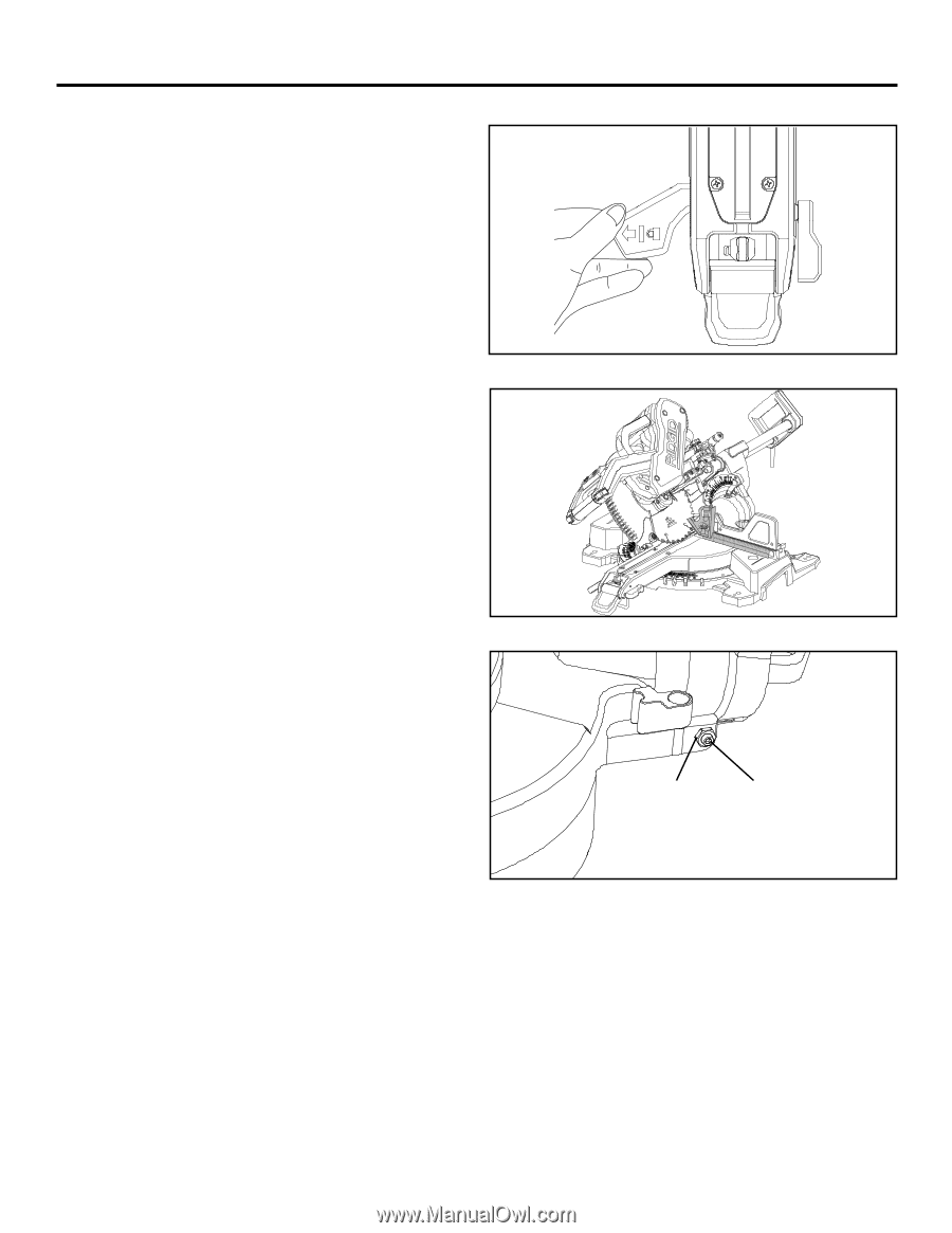
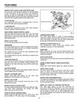
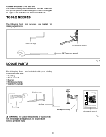
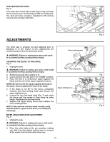
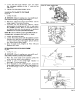
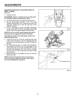
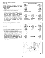
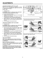
adjustments ADJUSTING THE BLADE TO THE MITER TABLE 45° BEVEL, 0° MITER Fig. 13-15 1. Unplug the saw. � WARNING: Failure to unplug your saw could result in accidental starting causing serious injury. 2. Lift the bevel-lock lever to release the bevel-lock. 3. Set the bevel-angle indicator to 45°. The miter indicator should point to 0°. Lower the saw arm and push the locking pin to lock the saw arm in the "DOWN" position. 4. Place a combination square (available separately) on the miter table with the rule against the table and the heel of the square against the saw blade. NOTE: Be sure to rest the square against the body of the blade, and not against the teeth of the blade. If the blade is not 45° to the miter table, perform the following adjustments: 5. Loosen the lock nut on the 45° stopping screw with a 3/8" open-end wrench. The 45° stopping bolts are located to your left and right as you face the back of the saw. 6. Lift the bevel-lock lever to release the bevel-lock, then adjust the blade to 45° by adjusting the set screws clockwise or counter-clockwise with a 3 mm hex key (not included). You may need to carefully move the saw arm left or right by hand while turning the set screw. 7. When the angle is set, tighten the lock nut and the bevel-lock lever. NOTE: If the bevel-lock lever does not secure the saw arm when it is tightened, please refer to BevelLock Lever Adjustment on page 16. Fig. 13 Fig. 14 Lock nut 45° Stopping screw Fig. 15 15
-
 1
1 -
2
-
3
-
4
-
5
-
6
-
7
-
8
-
9
-
10
-
 11
11 -
 12
12 -
 13
13 -
 14
14 -
 15
15 -
 16
16 -
 17
17 -
 18
18 -
 19
19 -
 20
20 -
 21
21 -
22
-
23
-
24
-
25
-
26
-
27
-
28
-
29
-
30
-
31
-
32
-
33
-
34
-
35
-
36
 |
 |