Ridgid MS255SR Operation Manual - Page 26
Compound Miter Cutting
 |
View all Ridgid MS255SR manuals
Add to My Manuals
Save this manual to your list of manuals |
Page 26 highlights
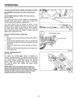
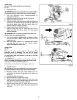
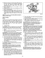
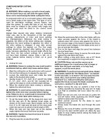
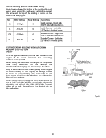
COMPOUND MITER CUTTING Fig. 28 � WARNING: When making a cut with a bevel angle, turn the lower fence out, and slide the upper sliding fence out to avoid having the blade cutting the fence. A compound miter cut is a cut made using a miter angle and a bevel angle at the same time. This type of cut is used for decorative moldings, picture frames, and other fine joinery. To make this type of cut, the miter table must be rotated to the correct miter angle and the saw arm must be tilted to the correct bevel angle. Always take special care when making compound miter cuts, due to the interaction of the two angle settings. Adjustments of miter and bevel settings are interdependent. Whenever the miter setting is adjusted, the effect of the bevel setting also changes. Whenever the bevel setting is adjusted, the effect of the miter setting is changed. It may take several settings to obtain the desired cut. The first angle setting should be checked after setting the second angle, because adjusting the second angle affects the first. Once the two correct settings for a particular cut have been obtained, always make a test cut in scrap material before making a finish cut in good material. 1. Unplug the saw. � WARNING: Failure to unplug the saw could result in accidental start up, which may cause serious injury. 2 Mark the cutting line on the work piece with a pencil. 3. Pull out the locking pin to release the saw arm. 4. Loosen the miter-lock lever and rotate the miter table to the desired miter angle. 5. Quickly locate 0°, 15°, 22.5°, 31.6° and 45° (for USA) 0°, 15°, 22.5°, 35.3°, and 45° (for Canada) left or right by the stops or clicks at these angle settings. 6. When the desired miter table setting is achieved, tighten the miter-lock lever. � WARNING: To avoid serious personal injury, always tighten the miter-lock lever securely before making a cut. Failure to do so could result in movement of the control arm or miter table while making a cut. 7. To set the bevel angle, lift the bevel-lock lever and tilt the saw arm to the desired bevel angle, as shown on the bevel scale. Bevel angles can be set from 0° to 45° right and left (pull out the stop plate under the saw arm to permit a bevel angle of 48°). 8. When the saw arm has been set at the desired angle, tighten the bevel-lock lever securely. � WARNING: Tighten the bevel-lock lever to secure the saw arm in position. 9. Plug the saw into an electrical outlet. Fig. 28 10. Place the work piece flat on the miter table, with one edge securely against the fence. If the board is warped, place the convex side against the fence. If the concave edge of the board is against the fence, the board could collapse on the blade at the end of the cut and jam the blade. 11. Turn on the laser and align the pencil line between the dual laser lines. 12. Use the work piece clamp to secure the work piece against the saw table and fence. 13. When cutting a long work piece, use a 3.5" block (not supplied) to support the long work piece. � CAUTION: Never use another person as an additional support for a work piece that is longer or wider than the basic saw table, or to help feed, support, or pull the work piece. � WARNING: To avoid serious personal injury, always keep hands outside the "No-Hands Zone," as marked on the saw table, or at least 3" (7.6 cm) away from the blade. Also, never perform any cutting operation "freehand" (i.e.; without holding the work piece against the fence), because the blade could grab the work piece, causing it to slip and twist. 14. Before turning the saw on, perform a trial of the cutting operation by lowering the saw arm to make sure that no problems will occur when the cut is made. 15. Raise the saw arm and, turn the saw on: press the lock-off button while squeezing the On/Off trigger switch located under the handle. 16. Allow several seconds for the blade to reach maximum speed. 17. Slowly lower the blade into and through the work piece. 18. Release the lock-off button and the trigger switch, and turn the laser On/Off switch off. Allow the saw blade to stop rotating before raising the blade out of the work piece. 25
-
 1
1 -
2
-
3
-
4
-
5
-
6
-
7
-
8
-
9
-
10
-
11
-
12
-
13
-
14
-
15
-
16
-
17
-
18
-
19
-
20
-
 21
21 -
 22
22 -
 23
23 -
 24
24 -
 25
25 -
 26
26 -
 27
27 -
 28
28 -
 29
29 -
 30
30 -
 31
31 -
32
-
33
-
34
-
35
-
36
 |
 |