Ridgid MS255SR Operation Manual - Page 17
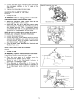
NOTE: Adjust the 33.9° for USA / 30° for Canada
 |
View all Ridgid MS255SR manuals
Add to My Manuals
Save this manual to your list of manuals |
Page 17 highlights
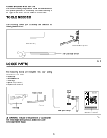
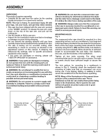
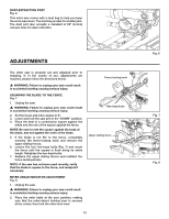
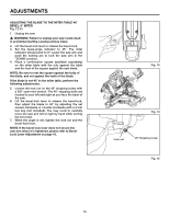
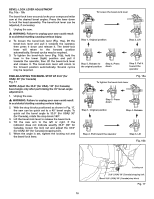
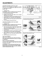
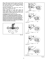
Bevel-Lock Lever Adjustment Fig. 16a - 16b The bevel-lock lever securely locks your compound miter saw at the desired bevel angles. Press the lever down to lock the head assembly. The bevel-lock lever can be adjusted, if necessary. 1. Unplug the saw. � WARNING: Failure to unplug your saw could result in accidental starting causing serious injury. 2. To loosen the bevel-lock lever (Fig. 16a), lift the bevel-lock lever and pull it towards the operator, then press it down and release it. The bevel-lock lever will return to the forward position automatically. Several cycles may be required. 3. To tighten the bevel-lock lever (Fig. 16b), hold the lever in the lower (tight) position and pull it towards the operator, then lift the bevel-lock lever and release it. The bevel-lock lever will return to the forward position automatically. Several cycles may be required. FINE ADJUSTING THE BEVEL STOP AT 33.9° (for USA)/ 30° (for Canada) Fig. 17 NOTE: Adjust the 33.9° (for USA) / 30° (for Canada) bevel angle only after performing the 45° bevel-angle adjustment. 1. Unplug the saw. � WARNING: Failure to unplug your saw could result in accidental starting causing serious injury. 2. With the stop blocks positioned as shown in Fig. 17, the saw can be quick set to a 45° bevel angle. To quick set the bevel angle to 33.9° (for USA)/ 30° (for Canada), rotate the stop block 180°. 3. Lift the bevel-lock lever to release the bevel-lock. 4. Tilt the saw arm to the left or right. If the indicator does not indicate exactly 33.9° (30° for Canada), loosen the lock nut and adjust the 33.9° (for USA)/ 30° (for Canada) stopping bolt. 5. When the angle is set, tighten the locking nut and the bevel-lock lever. To loosen the bevel-lock lever Step 1. Original position Step 2. Lift Step 5. Release to Step 4. Press the original position down Step 3. Pull it toward the operator To tighten the bevel-lock lever Fig. 16a Step 5. Press down Step 1. Original position Step 4. Release Step 2. Pull toward the operator Step 3. Lift Fig. 16b Locking nut 33.9° (USA)/ 30° (Canada) stopping bolt Bevel 33.9° (USA)/ 30° (Canada) stop block Fig. 17 16
-
 1
1 -
2
-
3
-
4
-
5
-
6
-
7
-
8
-
9
-
10
-
11
-
 12
12 -
 13
13 -
 14
14 -
 15
15 -
 16
16 -
 17
17 -
 18
18 -
 19
19 -
 20
20 -
 21
21 -
 22
22 -
23
-
24
-
25
-
26
-
27
-
28
-
29
-
30
-
31
-
32
-
33
-
34
-
35
-
36
 |
 |
