Ridgid MS255SR Operation Manual - Page 15
Squaring The Blade To The Table
 |
View all Ridgid MS255SR manuals
Add to My Manuals
Save this manual to your list of manuals |
Page 15 highlights
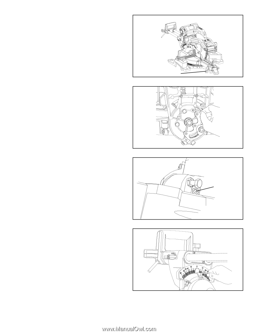
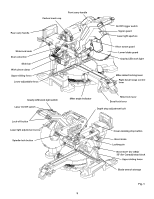
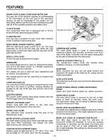
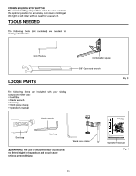
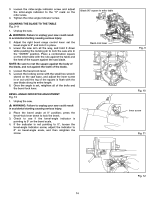
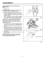
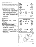
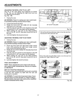
3. Loosen the miter-angle indicator screw and adjust the miter-angle indicator to the "0" mark on the miter scale. 4. Tighten the miter-angle indicator screw. SQUARING THE BLADE TO THE TABLE Fig. 9-11 1. Unplug the saw. � WARNING: Failure to unplug your saw could result in accidental starting causing serious injury. 2. Adjust the right bevel range control lever: set the bevel angle to 0° and lock it in place. 3. Lower the saw arm all the way, and hold it down while pushing the locking pin to lock the saw arm in the "DOWN" position. Place a combination square on the miter table with the rule against the table and the heel of the square against the saw blade. NOTE: Be sure to rest the square against the body of the blade, and not against the teeth of the blade. 4. Loosen the bevel-lock lever. 5. Loosen the locking screw with the small hex wrench stored on the saw base, and adjust the inner screw in or out until the leg of the square is flush with the saw blade along its entire length. 6. Once the angle is set, retighten all of the bolts and the bevel-lock lever. BEVEL-ANGLE INDICATOR ADJUSTMENT Fig. 12 1. Unplug the saw. � WARNING: Failure to unplug your saw could result in accidental starting causing serious injury. 2. Place the bevel angle at 0° position; press the bevel-lock lever down to lock the bevel. 3. Check to see if the bevel-angle indicator is pointing to 0° on the bevel scale. 4. If the indicator is not pointing to 0°, loosen the bevel-angle indicator screw, adjust the indicator to 0° on bevel-angle scale, and then retighten the screw. Blade 90° square to miter table Bevel-lock lever Fig. 9 Fig. 10 Inner screw Fig. 11 Fig. 12 14
-
 1
1 -
2
-
3
-
4
-
5
-
6
-
7
-
8
-
9
-
 10
10 -
 11
11 -
 12
12 -
 13
13 -
 14
14 -
 15
15 -
 16
16 -
 17
17 -
 18
18 -
 19
19 -
 20
20 -
21
-
22
-
23
-
24
-
25
-
26
-
27
-
28
-
29
-
30
-
31
-
32
-
33
-
34
-
35
-
36
 |
 |