Ridgid MS255SR Operation Manual - Page 11
Know Your Sliding Compound Miter Saw - blade change
 |
View all Ridgid MS255SR manuals
Add to My Manuals
Save this manual to your list of manuals |
Page 11 highlights
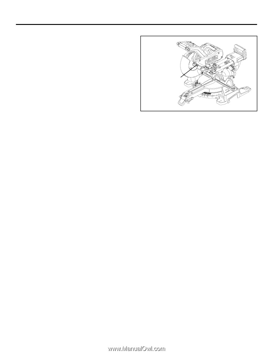
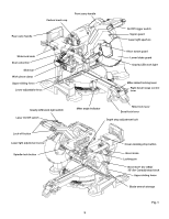
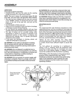
FEATURES KNOW YOUR SLIDING COMPOUND MITER SAW The safe use of this product requires an understanding of the information on the tool and in this operator's manual, as well as knowledge of the project you are attempting. Before use of this product, familiarize yourself with all of the operating features and safety rules. 10 inch blade Your compound miter saw is equipped with a 10-inch Freud 40-tooth, general purpose blade. Spindle-lock button 15 AMP motor This saw has a powerful 15 amp motor with sufficient power to handle tough cutting jobs. Right bevel range control LEVER With the right bevel range control lever "up" the head assembly can tilt to the left side only. Press the right bevel range control lever down and the saw arm can tilt both right and left. Bevel-lock lever To lock the saw at desired bevel angles. wrenches The larger blade wrench is used for changing the blade. One end of the blade wrench is a Phillips screwdriver and the other end is a hex key. The smaller hex key is used for laser adjustment and for miter 0° fine adjustment. The storage area for the two wrenches is located in the saw's base. CarRying handles For convenience when carrying or transporting the miter saw from one place to another, carrying handles are located on the top of the saw arm and the end of the slide bar. Fig. 2 LOWER BLADE GUARD The lower blade guard is made of shock-resistant, translucent plastic that provides protection from each side of the blade. It retracts over the upper blade guard as the saw is lowered into the work piece. SPINDLE-LOCK BUTTON (Fig. 2) The spindle-lock button locks the spindle while installing, changing, or removing blades. SLIDE BAR When unlocked, the saw arm will glide forward and backward the length of the slide bar for cutting various work-piece widths. SLIDE-LOCK KNOB The slide-lock knob locks and unlocks the sliding feature of this tool. Upper Sliding Fence/ Lower ADJUSTABLE Fence Upper and lower fences adjust for added precision. Electric brake The electric brake quickly stops blade rotation after the On/Off trigger switch is released. Gravity LED Work Light Unique work light that shines on the work area regardless of the position of the saw arm. MITER-LOCK LEVER The miter-lock lever securely locks the saw at the desired miter angle. Work piece CLAMP The work piece clamp is mounted on the left or right fence or base to securely clamp the work piece. The work piece clamp can be turned to different angles along the X-axis and Y-axis. Depth-stop adjustment BOLT The depth-stop adjustment is a feature used when cutting grooves in the work piece. The depth adjustment is used to limit the blade depth. MITER-DETENT LOCKING LEVER The miter-detent locking lever, when used with the miterlock lever lifted (unlocked), can release the miter table from pre-set index points. POSITIVE STOPS ON MITER TABLE Positive stops at right and left 0°, 15°, 22.5°, 31.6°, and 45° (for USA) / 0°, 15°, 22.5°, 35.3°, 45° (for Canada). BEVEL 33.9° (USA)/ 30° (CANADA) STOP BLOCK Use this stop block to set the saw-arm at bevel 33.9° (USA)/ 30° (Canada). To cut crown molding horizontally or vertically, use the bevel stop block and set the miter to 31.6° left or right (USA)/miter 35.3° left or right (Canada). This setting can also be used to cut flat wood stock. 10
-
 1
1 -
2
-
3
-
4
-
5
-
 6
6 -
 7
7 -
 8
8 -
 9
9 -
 10
10 -
 11
11 -
 12
12 -
 13
13 -
 14
14 -
 15
15 -
 16
16 -
17
-
18
-
19
-
20
-
21
-
22
-
23
-
24
-
25
-
26
-
27
-
28
-
29
-
30
-
31
-
32
-
33
-
34
-
35
-
36
 |
 |