Sanyo PDG-DET100L Instruction Manual, PDG-DET100L POA-MD13NET2 - Page 82
Port Specification
 |
UPC - 086483074684
View all Sanyo PDG-DET100L manuals
Add to My Manuals
Save this manual to your list of manuals |
Page 82 highlights
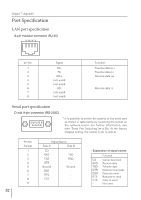
Chapter 7 Appendix Port Specification LAN port specification 8-pin modular connector (RJ-45) 12 345678 pin No. 1 2 3 4 5 6 7 8 Signal TX+ TXRD+ (not used) (not used) RD(not used) (not used) Function Transfer data (+) Transfer data (-) Receive data (+) Receive data (-) Serial port specification D sub 9-pin connector (RS-232C) 54 321 9876 * It is possible to switch the polarity of the serial port as shown in table below by switching the socket on the network board. For further information, see item "Serial Port Switching" (☞ p.65). At the factory shipped setting, the socket is set to side A. Pin No. Socket 1 2 3 4 5 6 7 8 9 Signal Name Side A Side B CD RXD TXD DTR Ground DSR RTS CTS - TXD RXD Ground - 82 - Explanation of signal names Function CD RXD TXD DTR DSR RTS CTS - Carrier detection Receive data Transfer data Data terminal ready Data set ready Request to send Clear to send Not used
-
 1
1 -
2
-
3
-
4
-
5
-
6
-
7
-
8
-
9
-
10
-
11
-
12
-
13
-
14
-
15
-
16
-
17
-
18
-
19
-
20
-
21
-
22
-
23
-
24
-
25
-
26
-
27
-
28
-
29
-
30
-
31
-
32
-
33
-
34
-
35
-
36
-
37
-
38
-
39
-
40
-
41
-
42
-
43
-
44
-
45
-
46
-
47
-
48
-
49
-
50
-
51
-
52
-
53
-
54
-
55
-
56
-
57
-
58
-
59
-
60
-
61
-
62
-
63
-
64
-
65
-
66
-
67
-
68
-
69
-
70
-
71
-
72
-
73
-
74
-
75
-
76
-
 77
77 -
 78
78 -
 79
79 -
 80
80 -
 81
81 -
 82
82 -
 83
83 -
 84
84 -
 85
85 -
 86
86 -
 87
87 -
88
-
89
-
90
-
91
-
92
 |
 |
