Sharp MX-M363N Installation Manual - Page 105
Removal of the table glass, the paper exit cover, Installation of the scanner heater unit
 |
View all Sharp MX-M363N manuals
Add to My Manuals
Save this manual to your list of manuals |
Page 105 highlights
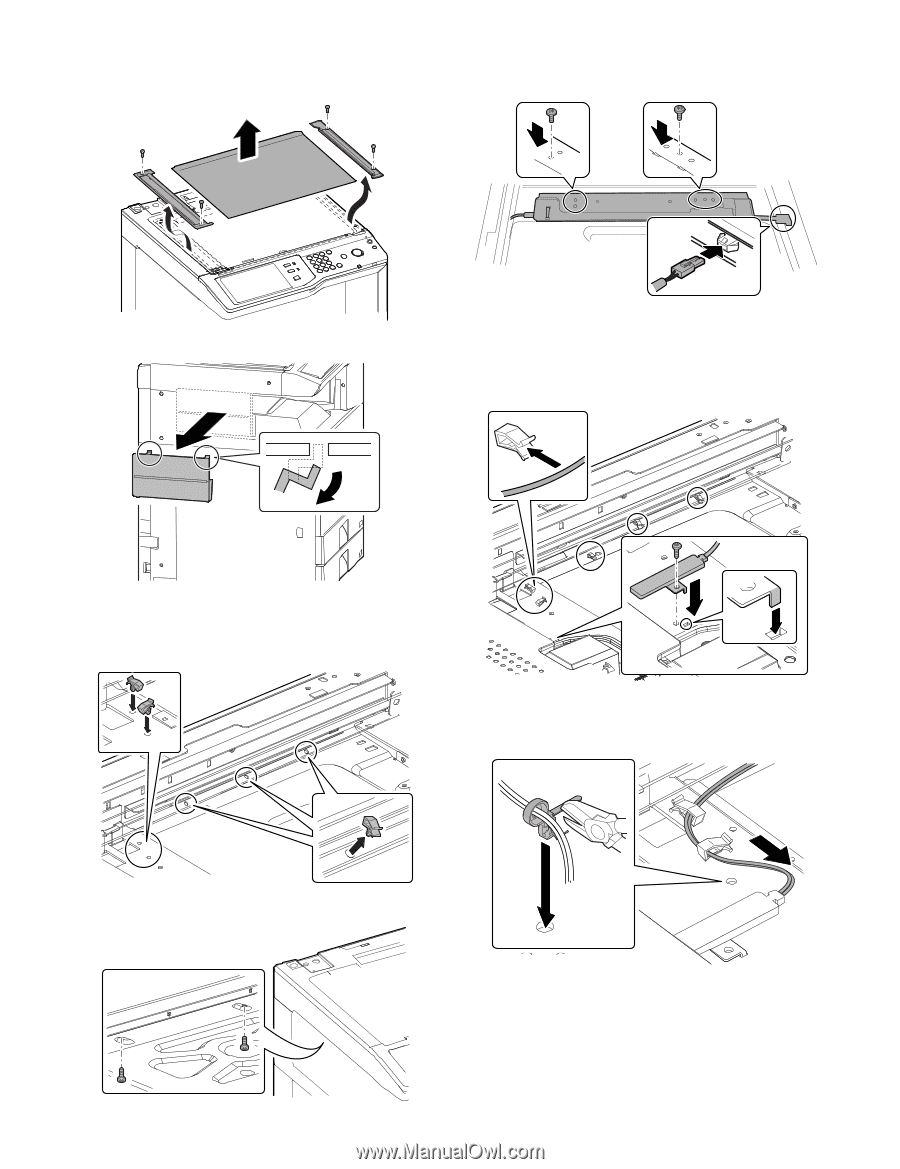
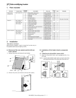
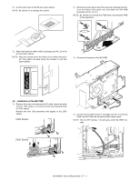
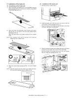
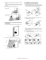
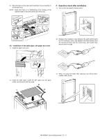
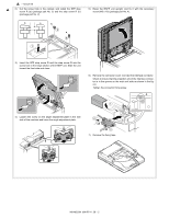
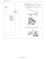
(2) Removal of the table glass, the paper exit cover 1) Remove the screw, and remove the SPF glass and the glass holder. Remove the table glass. 3) Connect the harness of the scanner heater. Install the heater fixing plate of the scanner heater unit, and secure it with the screw (M3x4 Round-tipped) (package part No. 17). 2) Remove the paper exit cover. 4) Install the scanner heater and secure it with the screw (M4x6 Bind machine screw) (package part No. 18). Pass the harness through the clamp. NOTE: The convex part of the scanner heater must be inserted into the hole of the scanner frame. (3) Installation of the scanner heater unit 1) Attach the clamp (package part No. 16) to the scanner frame. NOTE: When installing, be careful to prevent damage of the wire. 5) Tighten the loose scanner heater harness by pulling it in the arrow direction and secure it with the snap band (packing part No. 19) then cut its tip to approx. 5 mm or less. 2) Remove two screws from the scanner bottom. MX-M503N Dehumidifying heater 27 - 5
-
 1
1 -
2
-
3
-
4
-
5
-
6
-
7
-
8
-
9
-
10
-
11
-
12
-
13
-
14
-
15
-
16
-
17
-
18
-
19
-
20
-
21
-
22
-
23
-
24
-
25
-
26
-
27
-
28
-
29
-
30
-
31
-
32
-
33
-
34
-
35
-
36
-
37
-
38
-
39
-
40
-
41
-
42
-
43
-
44
-
45
-
46
-
47
-
48
-
49
-
50
-
51
-
52
-
53
-
54
-
55
-
56
-
57
-
58
-
59
-
60
-
61
-
62
-
63
-
64
-
65
-
66
-
67
-
68
-
69
-
70
-
71
-
72
-
73
-
74
-
75
-
76
-
77
-
78
-
79
-
80
-
81
-
82
-
83
-
84
-
85
-
86
-
87
-
88
-
89
-
90
-
91
-
92
-
93
-
94
-
95
-
96
-
97
-
98
-
99
-
 100
100 -
 101
101 -
 102
102 -
 103
103 -
 104
104 -
 105
105 -
 106
106 -
 107
107 -
 108
108 -
 109
109 -
 110
110 -
111
-
112
-
113
-
114
-
115
-
116
-
117
 |
 |