Sharp MX-M363N Installation Manual - Page 66
MX-TRX2, 1. Unpacking, A. Removal of the exit tray unit, B. Check the packed items, 2. Installation
 |
View all Sharp MX-M363N manuals
Add to My Manuals
Save this manual to your list of manuals |
Page 66 highlights
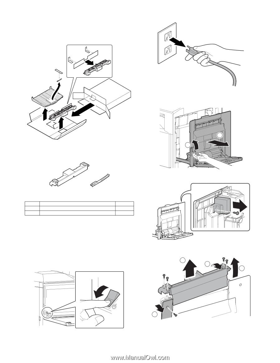
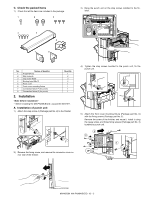
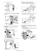
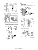
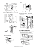
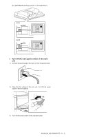
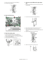
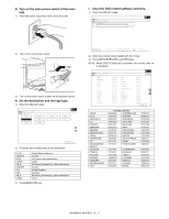
[M1X1-M]50M3NX-TRX2 1. Unpacking A. Removal of the exit tray unit S3)erRveimcoeve tMhae npouwaelr plug of the main unit from the outlet. B. Installation of the exit roller unit 1) Open the right door. B. Check the packed items 1) Check that all the items are included in the package. 2 1 1 2 No. Packed part names 1 Exit roller unit 2 Full detection actuator Quantity 1 1 2. Installation * Before starting installation, check to insure that the data lamp on the operation panel does not light up or blink. A. Turn off the power of the main unit 1) Turn OFF the power switch on the operation panel. 2) Open the front cabinet. Turn OFF the power switch in the front cabinet of the main unit. 2) Remove the screw, and remove the connector cover. 3) Remove the screw. Disengage the engagement in the front side then in the rear side, and remove the paper exit cover. 4 1 2 OFF 3 MX-M503N MX-TRX2 11 - 1
-
 1
1 -
2
-
3
-
4
-
5
-
6
-
7
-
8
-
9
-
10
-
11
-
12
-
13
-
14
-
15
-
16
-
17
-
18
-
19
-
20
-
21
-
22
-
23
-
24
-
25
-
26
-
27
-
28
-
29
-
30
-
31
-
32
-
33
-
34
-
35
-
36
-
37
-
38
-
39
-
40
-
41
-
42
-
43
-
44
-
45
-
46
-
47
-
48
-
49
-
50
-
51
-
52
-
53
-
54
-
55
-
56
-
57
-
58
-
59
-
60
-
 61
61 -
 62
62 -
 63
63 -
 64
64 -
 65
65 -
 66
66 -
 67
67 -
 68
68 -
 69
69 -
 70
70 -
 71
71 -
72
-
73
-
74
-
75
-
76
-
77
-
78
-
79
-
80
-
81
-
82
-
83
-
84
-
85
-
86
-
87
-
88
-
89
-
90
-
91
-
92
-
93
-
94
-
95
-
96
-
97
-
98
-
99
-
100
-
101
-
102
-
103
-
104
-
105
-
106
-
107
-
108
-
109
-
110
-
111
-
112
-
113
-
114
-
115
-
116
-
117
 |
 |