Sony HVR-Z5E Operation Guide - Page 10
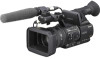
When the CH1 switch is set to, INT MIC, When the CH1 is, set to INPUT1
 |
View all Sony HVR-Z5E manuals
Add to My Manuals
Save this manual to your list of manuals |
Page 10 highlights
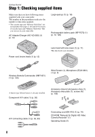
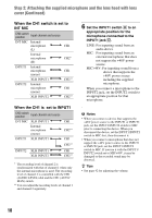
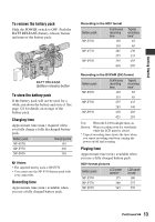
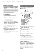
Step 2: Attaching the supplied microphone and the lens hood with lens cover (Continued) When the CH1 switch is set to INT MIC CH2 switch position Input channel and source INT MIC Internal microphone CH1 (L) Internal microphone (R) CH2* INPUT1 Internal microphone (mono) XLR INPUT1 CH1 CH2** INPUT2 Internal microphone (mono) XLR INPUT2 CH1 CH2** When the CH1 is set to INPUT1 CH2 switch position Input channel and source INT MIC XLR INPUT1 Internal microphone (mono) INPUT1 XLR INPUT1 CH1 CH2** CH1 CH2** INPUT2 XLR INPUT1 XLR INPUT2 CH1 CH2** * The recording level of channel 2 is synchronized with that of channel 1 when only the internal microphone is used. The recording level of channel 2 is controlled with the CH1 (AUDIO LEVEL) dial and the CH1 (AUTO/ MAN) switch. ** You can adjust the recording levels of channel 1 and channel 2 separately. 6 Set the INPUT1 switch H to an appropriate position for the microphone connected to the INPUT1 jack D. LINE: For inputting sound from an audio device MIC: For inputting sound from an external microphone that does not support the +48V power source. MIC+48V: For inputting sound from a device that supports the +48V power source including the supplied microphone. When you connect a microphone to the INPUT2 jack, set the INPUT2 switch to an appropriate position for that microphone. b Notes • When you connect a device that supports the +48V power source to the INPUT1 or INPUT2 jack, set the INPUT1/INPUT2 switch to MIC prior to connecting the device. When you disconnect the device, set the INPUT1/INPUT2 switch to MIC first, then disconnect it. • When you connect a microphone that does not support the +48V power source to the INPUT1 or INPUT2 jack, set the INPUT1/INPUT2 switch to MIC. If you use it with the INPUT1/ INPUT2 switch set to MIC+48V, it may be damaged or the recorded sound may be distorted. z Tips • See page 42 for adjusting the volume. 10
-
 1
1 -
2
-
3
-
4
-
 5
5 -
 6
6 -
 7
7 -
 8
8 -
 9
9 -
 10
10 -
 11
11 -
 12
12 -
 13
13 -
 14
14 -
 15
15 -
16
-
17
-
18
-
19
-
20
-
21
-
22
-
23
-
24
-
25
-
26
-
27
-
28
-
29
-
30
-
31
-
32
-
33
-
34
-
35
-
36
-
37
-
38
-
39
-
40
-
41
-
42
-
43
-
44
-
45
-
46
-
47
-
48
-
49
-
50
-
51
-
52
-
53
-
54
-
55
-
56
-
57
-
58
-
59
-
60
-
61
-
62
-
63
-
64
-
65
-
66
-
67
-
68
-
69
-
70
-
71
-
72
-
73
-
74
-
75
-
76
-
77
-
78
-
79
-
80
-
81
-
82
-
83
-
84
-
85
-
86
-
87
-
88
-
89
-
90
-
91
-
92
-
93
-
94
-
95
-
96
-
97
-
98
-
99
-
100
-
101
-
102
-
103
-
104
-
105
-
106
-
107
-
108
-
109
-
110
-
111
-
112
-
113
-
114
-
115
-
116
-
117
-
118
-
119
-
120
-
121
-
122
-
123
-
124
-
125
-
126
-
127
-
128
-
129
-
130
-
131
-
132
-
133
-
134
-
135
-
136
-
137
-
138
-
139
-
140
-
141
-
142
-
143
 |
 |
