Sony STR-DA7100ES Operating Instructions - Page 87
Operating Sony components, The CONTROL A1, Control, System
 |
View all Sony STR-DA7100ES manuals
Add to My Manuals
Save this manual to your list of manuals |
Page 87 highlights
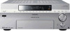
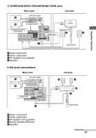
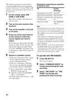
Operating Sony components The CONTROL A1II Control System The CONTROL A1II Control System was designed to simplify the operation of audio systems composed of separate Sony components. CONTROL A1II connections provide a path for the transmission of control signals which enable automatic operation and control features usually associated with integrated systems. Currently, CONTROL A1II connections between a Sony CD player, amplifier (receiver), MD deck and cassette deck provide automatic function selection. Note Do not operate a 2 way remote control unit when the CONTROL A1II jacks are connected via a PC interface kit to a personal computer running "MD Editor" or a similar application. Also, do not operate the connected component in a manner contrary to the functions of the application, as this may cause the application to operate incorrectly. CONTROL A1II and CONTROL A1 compatibility The CONTROL A1 control system has been updated to the CONTROL A1II system which is now the standard system for the Sony 300 disc CD changer and other recent Sony components. Components with CONTROL A1 jacks are compatible with components with CONTROL A1II, and can be connected to each other. Basically, the majority of the functions available with the CONTROL A1 control system will be available with the CONTROL A1II control system. However, when making connections between components with CONTROL A1 jacks and components with CONTROL A1II jacks, the number of functions that can be controlled may be limited depending on the component. For detailed information, refer to the operating instructions supplied with the component(s). If you have a Sony CD changer with a COMMAND MODE selector If your CD changer's COMMAND MODE selector can be set to CD 1, CD 2, or CD 3, be sure to set the command mode to "CD 1" and connect the changer to the CD jacks on the amplifier (receiver). If, however, you have a Sony CD changer with VIDEO OUT jacks, set the command mode to "CD 2" and connect the changer to the VIDEO 2 jacks on the amplifier (receiver). Connections You can connect up to 10 CONTROL A1II compatible components in any order. However, you can connect only one of each type of component (i.e., 1 CD player, 1 MD deck, 1 tape deck and 1 receiver). (You may be able to connect more than one CD player or MD deck, depending on the model. Refer to the operating instructions supplied with the respective component for details.) Example Amplifier CD MD (Receiver) player deck Tape Other deck components In the CONTROL A1II control system, the control signals flow both ways, so there is no distinction between IN and OUT jacks. If a component has more than one CONTROL A1II jack, you can use either one, or connect different components to each jack. Some CONTROL A1 compatible components are supplied with a connecting cord as an accessory. In this case, use the connecting cord for your connection. When using a commercially available cord, use a monaural (2P) mini-plug cord less than 2 meters long, with no resistance. continued 87GB Amplifier Operation
-
 1
1 -
2
-
3
-
4
-
5
-
6
-
7
-
8
-
9
-
10
-
11
-
12
-
13
-
14
-
15
-
16
-
17
-
18
-
19
-
20
-
21
-
22
-
23
-
24
-
25
-
26
-
27
-
28
-
29
-
30
-
31
-
32
-
33
-
34
-
35
-
36
-
37
-
38
-
39
-
40
-
41
-
42
-
43
-
44
-
45
-
46
-
47
-
48
-
49
-
50
-
51
-
52
-
53
-
54
-
55
-
56
-
57
-
58
-
59
-
60
-
61
-
62
-
63
-
64
-
65
-
66
-
67
-
68
-
69
-
70
-
71
-
72
-
73
-
74
-
75
-
76
-
77
-
78
-
79
-
80
-
81
-
 82
82 -
 83
83 -
 84
84 -
 85
85 -
 86
86 -
 87
87 -
 88
88 -
 89
89 -
 90
90 -
 91
91 -
 92
92 -
93
-
94
-
95
-
96
-
97
-
98
-
99
-
100
-
101
-
102
-
103
-
104
-
105
-
106
-
107
-
108
-
109
-
110
-
111
-
112
-
113
-
114
-
115
-
116
-
117
-
118
-
119
-
120
-
121
-
122
-
123
-
124
-
125
-
126
-
127
-
128
-
129
-
130
-
131
-
132
-
133
-
134
-
135
-
136
-
137
-
138
-
139
 |
 |
