Sony UPCR20L Operating Instructions - Page 14
Rear, Paper adapter blue
 |
View all Sony UPCR20L manuals
Add to My Manuals
Save this manual to your list of manuals |
Page 14 highlights
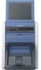
g Output cover Attach this to the output tray to prevent printouts from ejecting too far out of the output slot when printing. h Output slot Printouts are ejected from here. i Ribbon door (page 21) Open and close this when replacing the ink ribbon. This does not open when the unit is turned on. For details, see "Loading the Paper Roll and Ink Ribbon" on page 17. j Paper door (page 19) Open and close this when replacing paper rolls. This does not open while printing is in progress. k Paper door lever Use this to open the paper door. When the paper and ribbon doors are open Rear Chapter 2 Preparations a Filter cover The ventilation filter is located under here. b Display stand Use this stand to adjust the angle of the display. c Extension connector cover The connectors that are required when using extension functions are located under here. When the extension connector cover is open A Paper core Insert this into the paper roll. B Ribbon tray Place the ink ribbon here. C Paper adapter (blue) D Paper adapter (pink) Attach the paper adapters to the printer when using the 2UPC-R203/R205 series printing pack. l Scrap receptacle (page 22) Margins of empty space are crated between each printout. These margins are cut off during printing and dropped into this receptacle. 14 Controls and Functions A RS-232C connecter Allows connection of a commercially available thermal sheet printer or similar device. B USB port (device) (page 48) Use a commercially available USB cable to connect the unit to an SX-WSG1, computer, or similar device.1) 1) Operation is not guaranteed when connected by a USB hub.
-
 1
1 -
2
-
3
-
4
-
5
-
6
-
7
-
8
-
 9
9 -
 10
10 -
 11
11 -
 12
12 -
 13
13 -
 14
14 -
 15
15 -
 16
16 -
 17
17 -
 18
18 -
 19
19 -
20
-
21
-
22
-
23
-
24
-
25
-
26
-
27
-
28
-
29
-
30
-
31
-
32
-
33
-
34
-
35
-
36
-
37
-
38
-
39
-
40
-
41
-
42
-
43
-
44
-
45
-
46
-
47
-
48
-
49
-
50
-
51
-
52
-
53
-
54
-
55
-
56
-
57
-
58
-
59
-
60
-
61
-
62
-
63
-
64
-
65
-
66
-
67
-
68
-
69
-
70
-
71
-
72
-
73
-
74
-
75
-
76
-
77
-
78
-
79
-
80
-
81
 |
 |
