Sony VPL-CX76 Operating Instructions - Page 8
Connector Panel, Wireless LAN card slot VPL - wireless projector
 |
UPC - 027242666238
View all Sony VPL-CX76 manuals
Add to My Manuals
Save this manual to your list of manuals |
Page 8 highlights
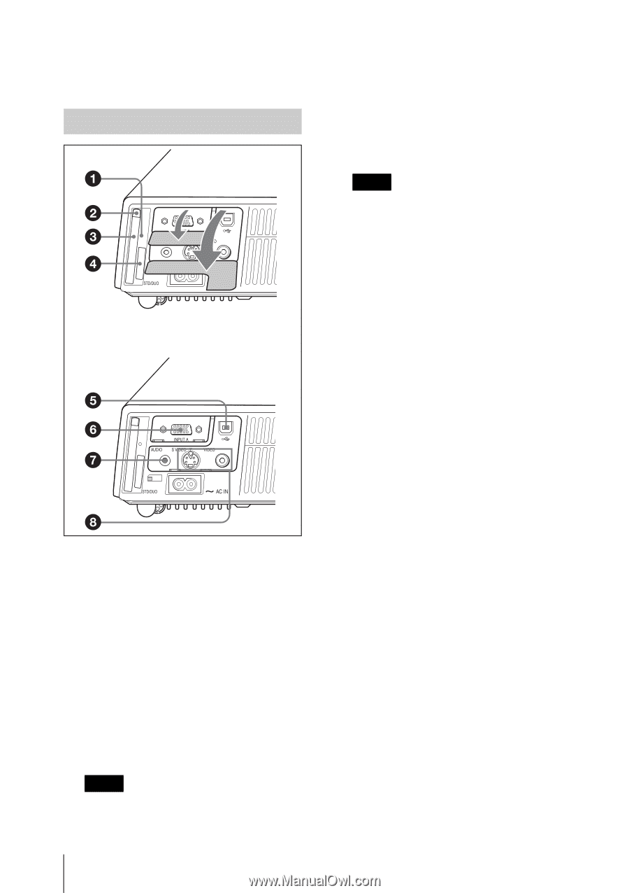
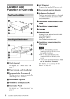
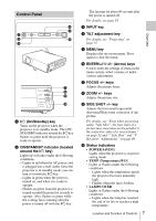
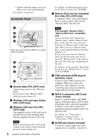
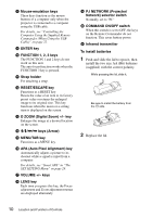
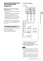
- Flashes when the lamp cover or air filter cover is not secured firmly. For details, see page 42. Connector Panel Open the cover to use the INPUT A or Video input connectors. a Access lamp (VPL-CX76 only) Lights during access to the "Memory Stick". Do not remove the "Memory Stick" while the access lamp is lit. b Wireless LAN card eject button (VPL-CX76 only) c Wireless LAN card slot (VPLCX76 only) The supplied wireless LAN card can be inserted. Never insert anything other than the supplied wireless LAN card. Note Remove the wireless LAN card from the wireless LAN card slot when storing the projector in the carrying case. 8 Location and Function of Controls For details, see Operating Instructions for Air Shot (stored on the CD-ROM). d Memory Stick slot (for standard/ Duo size) (VPL-CX76 only) A "Memory Stick" can be inserted here. Never insert an object other than the "Memory Stick" into this slot. Note (The standard "Memory Stick"/ "Memory Stick Duo" compatible slot) You can use both of the standard size "Memory Stick" and the "Memory Stick Duo" in the same slot. (You cannot use both sizes of "Memory Stick" at the same time.) When you use a "Memory Stick Duo", do not attach the Memory Stick Duo Adaptor to it. Do not insert more than one "Memory Stick" into the slot at the same time or insert the "Memory Stick" in the opposite direction. This will cause a malfunction of this unit. For details, see the attached "Operating Instructions for "Memory Stick"" stored on the CD-ROM. e USB connector (USB plug for upstream, 4-pin) Connects to the USB connector of a computer. When you connect the projector to the computer, you can control the mouse function with the supplied Remote Commander. f INPUT A connector (HD D-sub 15-pin, female) Inputs a computer signal, video GBR signal, component signal, or DTV signal depending on the connected equipment. Connects to the output connector of equipment using the supplied cable or an optional cable. For details, see "Connecting a Computer" on page 13 and "Connecting a VCR" on page 14. g AUDIO jack (stereo minijack) To listen to sound output from video equipment or a computer, connect via
-
 1
1 -
2
-
 3
3 -
 4
4 -
 5
5 -
 6
6 -
 7
7 -
 8
8 -
 9
9 -
 10
10 -
 11
11 -
 12
12 -
 13
13 -
14
-
15
-
16
-
17
-
18
-
19
-
20
-
21
-
22
-
23
-
24
-
25
-
26
-
27
-
28
-
29
-
30
-
31
-
32
-
33
-
34
-
35
-
36
-
37
-
38
-
39
-
40
-
41
-
42
-
43
-
44
-
45
-
46
-
47
-
48
-
49
-
50
-
51
-
52
-
53
-
54
 |
 |