Symphonic SF225A Owner's Manual - Page 11
Continued,
 |
View all Symphonic SF225A manuals
Add to My Manuals
Save this manual to your list of manuals |
Page 11 highlights
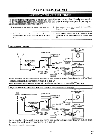
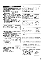
Fig.3: VHF/UHF Separate Antenna [UHF antenna] [VHF antenna] [Back of the VCR] To VCR's ANT.IN (Top Jack) ANT [Back of the UHFNHF combination TV] (New S le) O 0 UHFNHF UHFNHF combiner (not s lied 0 UHF (300ohm) VHF (75ohm) CV CHI l III OR Coaxial cable (supplied) [Back of the UHFNHF separated TV] Old S le UHFNHF separator (not supplied) To VCR's ANT.OUT (Bottom Jack) Coaxial cable (supplied) I " MI6 OVHF O OUHF You can record one channel while viewing another. The same goes for Automatic Timer Recording and One Touch Recording. For details, please refer to "Recording" on page 20. Fig.4: Cable Box and Satellite Box [Cable Box or Satellite Box] IN Jack OUT Jack [Back of the VCR] To VCR's ANT.IN (Top Jack) [Back of the UHFNHF combination TV] (New Style) O UHFNHF IN 0 Coaxial cable (supplied) [Back of the OR Cla UHFNHF separated TV] Old S le UHFNHF separator (not supplied) To VCR's ANT.OUT VHF (Bottom Jack) Coaxial cable UHF ®VHF ® UHF (supplied) You can ONLY record and view the SAME channel when using this connection. There are no exceptions. The same goes for Automatic Timer Recording and One Touch Recording. Note: Channel memory programming is NOT needed when using this connection. RECORDING HINTS 1) Be sure to check that the "PWR." and the "VCR" indicators are both on. 2) Turn on the TV and Cable Box or Satellite Box. 3) Set the channel to be recorded on the Cable Box or Satellite Box. 4) Set the TV and VCR to channel 3 or 4. 5) Set the CH3/CH4 switch on the back of the VCR to match the channel set on the TV and VCR. 6) Press the RECORD button. For AUTOMATIC TIMER RECORDING, the VCR must stay on channel 3 or 4 at step [9] on page 23. Continued on the next page. -11- EN 9121
-
 1
1 -
2
-
3
-
4
-
5
-
 6
6 -
 7
7 -
 8
8 -
 9
9 -
 10
10 -
 11
11 -
 12
12 -
 13
13 -
 14
14 -
 15
15 -
 16
16 -
17
-
18
-
19
-
20
-
21
-
22
-
23
-
24
-
25
-
26
-
27
-
28
-
29
-
30
-
31
-
32
-
33
-
34
-
35
-
36
-
37
-
38
-
39
-
40
-
41
-
42
-
43
-
44
 |
 |
