TEAC AI-303 Owners Manual English Francais Espanol - Page 11
Main unit parts and functions, Standby/on, button, PHONES jack, SOURCE button, Input source indicators
 |
View all TEAC AI-303 manuals
Add to My Manuals
Save this manual to your list of manuals |
Page 11 highlights
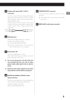
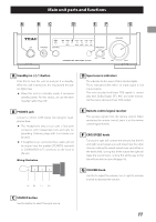
Main unit parts and functions A Standby/on (¤) button Press this to turn the unit on and put it in standby. When the unit is turned on, the ring around the button lights blue. oo When this unit is in standby mode, it consumes standby power. For this reason, we use the term "standby" rather than "off". B PHONES jack Connect a 3.5mm (1/8") stereo mini plug for headphones here. oo This headphone amp circuit uses a four-pole connector with independent left and right for grounding. Ordinary plugs with 3 or 4 poles can be used. oo If headphones are connected here, audio will not be output from the speaker (SPEAKERS) terminals or SUBWOOFER OUT connector on the back of the unit. Wiring illustration L+ R+ L− R− D Input source indicators The indicator for the source that is selected lights. These indicators blink when an input signal is not input properly. This unit can play back linear PCM signals. It cannot play back Dolby Digital, DTS, AAC and other formats. Set the source device to linear PCM output. E Remote control signal receiver This receives signals from the remote control. When operating the remote control, point it at the remote control signal receiver. F CROSSFEED knob Turning this right will increase the amount that the left and right sound signals are each mixed into the other channel, making the overall sound more centralized in the stereo field. Turning this all the way to the right will make the sound mono. Turning this all the way to the left will turn this function off (page 14). G VOLUME knob Use this to adjust the volume. Turn it right to increase and left to decrease the volume. C SOURCE button Use this button to select the input source. 11
-
 1
1 -
2
-
3
-
4
-
5
-
 6
6 -
 7
7 -
 8
8 -
 9
9 -
 10
10 -
 11
11 -
 12
12 -
 13
13 -
 14
14 -
 15
15 -
 16
16 -
17
-
18
-
19
-
20
-
21
-
22
-
23
-
24
-
25
-
26
-
27
-
28
-
29
-
30
-
31
-
32
-
33
-
34
-
35
-
36
-
37
-
38
-
39
-
40
-
41
-
42
-
43
-
44
-
45
-
46
-
47
-
48
-
49
-
50
-
51
-
52
-
53
-
54
-
55
-
56
-
57
-
58
-
59
-
60
-
61
-
62
-
63
-
64
-
65
-
66
-
67
-
68
-
69
-
70
-
71
-
72
-
73
-
74
-
75
-
76
 |
 |
