TRENDnet TPE-1020WS User's Guide - Page 74
PoE Configuration, Power Ranges of the PDs
 |
View all TRENDnet TPE-1020WS manuals
Add to My Manuals
Save this manual to your list of manuals |
Page 74 highlights
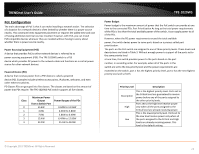
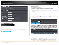
TRENDnet User's Guide PoE Configuration The main advantage of PoE is that it can make installing a network easier. The selection of a location for a network device is often limited by whether there is a power source nearby. This constraint limits equipment placement or requires the added time and cost of having additional electrical sources installed. However, with PoE, you can install PoEcompatible devices wherever they are needed without having to worry about whether there is power source nearby. Power Sourcing Equipment (PSE) A device that provides PoE to other network devices is referred to as power sourcing equipment (PSE). The TPE-1020WS switch is a PSE device which provides DC power to the network cable and functions as a central power source for other network devices. Powered Device (PD) A device that receives power from a PSE device is called a powered device (PD). Examples include wireless access points, IP phones, webcams, and even other Ethernet switches. PD Classes PDs are grouped into five classes. The classes are based on the amount of power that PDs require. The TPE-1020WS PoE switch supports all five classes. Class 0 1 2 3 4 Maximum Power Output from a Switch Port 15.4W 4.0W 7.0W 15.4W 34.2W Power Ranges of the PDs 0.44W to 12.95W 0.44W to 3.84W 3.84W to 6.49W 6.49W to 12.95W 25.5W to 38.9W TPE-1020WS Power Budget Power budget is the maximum amount of power that the PoE switch can provide at one time to the connected PDs. Port Prioritization As long as the total power requirements of the PDs is less than the total available power of the switch, it can supply power to all of the PDs. However, when the PD power requirements exceed the total available power, the switch denies power to some ports based on a process called port prioritization. The ports on the PoE switch are assigned to one of three priority levels. These levels and descriptions are listed in Table 3. Without enough power to support all the ports set to the same priority level at one time, the switch provides power to the ports based on the port number, in ascending order. For example, when all of the ports in the switch are set to the low priority level and the power requirements are exceeded on the switch, port 1 has the highest priority level, port 2 has the next highest priority level and so forth. Priority Level Description Description High Low This is the highest priority level. Ports set to the Critical level are guaranteed to receive power before any of the ports assigned to the other priority levels. Ports set to the High level receive power only when all the ports assigned to the Critical level are already receiving power. This is the lowest priority level. Ports set to the Low level receive power only when all the ports assigned to the Critical and High levels are already receiving power. This level is the default setting. © Copyright 2013 TRENDnet. All Rights Reserved. 74
-
 1
1 -
2
-
3
-
4
-
5
-
6
-
7
-
8
-
9
-
10
-
11
-
12
-
13
-
14
-
15
-
16
-
17
-
18
-
19
-
20
-
21
-
22
-
23
-
24
-
25
-
26
-
27
-
28
-
29
-
30
-
31
-
32
-
33
-
34
-
35
-
36
-
37
-
38
-
39
-
40
-
41
-
42
-
43
-
44
-
45
-
46
-
47
-
48
-
49
-
50
-
51
-
52
-
53
-
54
-
55
-
56
-
57
-
58
-
59
-
60
-
61
-
62
-
63
-
64
-
65
-
66
-
67
-
68
-
 69
69 -
 70
70 -
 71
71 -
 72
72 -
 73
73 -
 74
74 -
 75
75 -
 76
76 -
 77
77 -
 78
78 -
 79
79 -
80
-
81
-
82
-
83
-
84
-
85
-
86
-
87
-
88
-
89
-
90
-
91
-
92
-
93
-
94
-
95
-
96
-
97
-
98
-
99
-
100
-
101
-
102
-
103
-
104
-
105
 |
 |
