Tanaka TCG22EADSLP Owner's Manual - Page 2
metal/rigid
 |
View all Tanaka TCG22EADSLP manuals
Add to My Manuals
Save this manual to your list of manuals |
Page 2 highlights
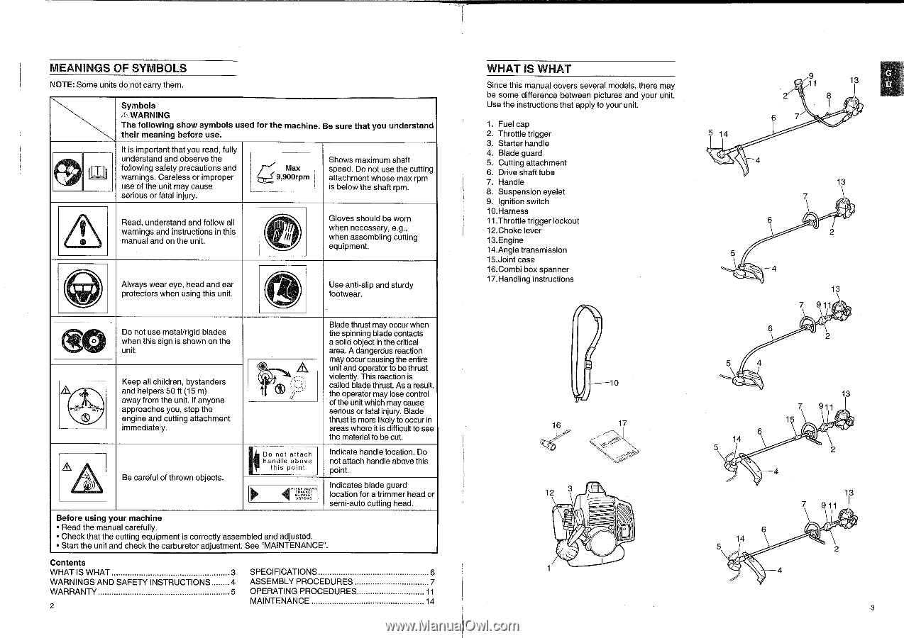
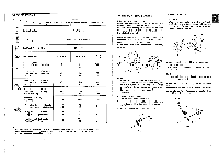
MEANINGS OF SYMBOLS NOTE: Some units do not carry them. 1)(#0, dm, It/ HI----!----1' 1 Symbols n. WARNING The following show symbols used for the machine. Be sure that you understand their meaning before use. It is important that you read, fully understand and observe the following safety precautions and warnings. Careless or improper use of the unit may cause serious or fatal injury. Max ,.._._, 9,900rpm Shows maximum shaft speed. Do not use the cutting attachment whose max rpm is below the shaft rpm. Read, understand and follow all warnings and instructions in this manual and on the unit. C Gloves should be worn when necessary, e.g., when assembling cutting equipment. pAilkNit Always wear eye, head and ear protectors when using this unit. Use anti-slip and sturdy footwear. O Do not use metal/rigid blades when this sign is shown on the unit. A t• Keep all children, bystanders and helpers 50 ft (15 m) away from the unit. If anyone approaches you, stop the engine and cutting attachment immediately. Be careful of thrown objects. 0) * 4 , f II Do not attach handle above this point 4'n "."' Blade thrust may occur when the spinning blade contacts a solid object in the critical area. A dangerous reaction may occur causing the entire unit and operator to be thrust violently. This reaction is called blade thrust. As a result, the operator may lose control of the unit which may cause serious or fatal injury. Blade thrust is more likely to occur in areas where it is difficult to see the material to be cut. Indicate handle location. Do not attach handle above this point. Indicates blade guard location for a trimmer head or semi-auto cutting head. Before using your machine • Read the manual carefully. • Check that the cutting equipment is correctly assembled and adjusted. • Start the unit and check the carburetor adjustment. See "MAINTENANCE". Contents WHAT IS WHAT 3 SPECIFICATIONS 6 WARNINGS AND SAFETY INSTRUCTIONS 4 ASSEMBLY PROCEDURES 7 WARRANTY 5 OPERATING PROCEDURES 11 2 MAINTENANCE 14 WHAT IS WHAT Since this manual covers several models, there may be some difference between pictures and your unit. Use the instructions that apply to your unit. 1. Fuel cap 2. Throttle trigger 3. Starter handle 4. Blade guard 5. Cutting attachment 6. Drive shaft tube 7. Handle 8. Suspension eyelet 9. Ignition switch 10. Harness 11.Throttle trigger lockout 12.Choke lever 13. Engine 14.Angle transmission 15.Joint case 16.Combi box spanner 17.Handling instructions 5 14 13 13 13 911 \I 16 17 12 OI 13 14 4 14 4 13 9 11 3
-
 1
1 -
 2
2 -
 3
3 -
 4
4 -
 5
5 -
 6
6 -
 7
7 -
 8
8 -
9
-
10
-
11
-
12
-
13
-
14
-
15
-
16
-
17
-
18
-
19
-
20
-
21
-
22
-
23
-
24
-
25
-
26
-
27
-
28
-
29
-
30
 |
 |