Toshiba Tecra M2-S519 Maintenance Manual - Page 235
Installing the Slim select bay module, plastic frame, screws, connector, slim select bay module
 |
View all Toshiba Tecra M2-S519 manuals
Add to My Manuals
Save this manual to your list of manuals |
Page 235 highlights
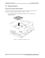
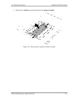
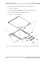
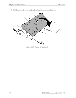
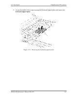
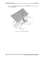
4.7 Slim select bay module 4 Replacement Procedures Installing the Slim select bay module To install the slim select bay module, follow the steps below and refer to figures 4-9 and 410. 1. Seat the plastic frame on the side of the slim select bay module, and secure it with the following screws. • M2×3S S-FLAT HEAD screw ×5 2. Install the connector and plastic brace and secure them with the following screws. • M2×8S BIND screw ×2 3. Insert the slim select bay module into the computer to connect it to the connector on the system board. 4. Remove the following screw from the screw hole. Then secure the latch with the removed screw. (The slim select bay is locked.) • M2.5×4B FLAT HEAD screw ×1 TECRA M2 Maintenance Manual (960-468) 4-21
-
 1
1 -
2
-
3
-
4
-
5
-
6
-
7
-
8
-
9
-
10
-
11
-
12
-
13
-
14
-
15
-
16
-
17
-
18
-
19
-
20
-
21
-
22
-
23
-
24
-
25
-
26
-
27
-
28
-
29
-
30
-
31
-
32
-
33
-
34
-
35
-
36
-
37
-
38
-
39
-
40
-
41
-
42
-
43
-
44
-
45
-
46
-
47
-
48
-
49
-
50
-
51
-
52
-
53
-
54
-
55
-
56
-
57
-
58
-
59
-
60
-
61
-
62
-
63
-
64
-
65
-
66
-
67
-
68
-
69
-
70
-
71
-
72
-
73
-
74
-
75
-
76
-
77
-
78
-
79
-
80
-
81
-
82
-
83
-
84
-
85
-
86
-
87
-
88
-
89
-
90
-
91
-
92
-
93
-
94
-
95
-
96
-
97
-
98
-
99
-
100
-
101
-
102
-
103
-
104
-
105
-
106
-
107
-
108
-
109
-
110
-
111
-
112
-
113
-
114
-
115
-
116
-
117
-
118
-
119
-
120
-
121
-
122
-
123
-
124
-
125
-
126
-
127
-
128
-
129
-
130
-
131
-
132
-
133
-
134
-
135
-
136
-
137
-
138
-
139
-
140
-
141
-
142
-
143
-
144
-
145
-
146
-
147
-
148
-
149
-
150
-
151
-
152
-
153
-
154
-
155
-
156
-
157
-
158
-
159
-
160
-
161
-
162
-
163
-
164
-
165
-
166
-
167
-
168
-
169
-
170
-
171
-
172
-
173
-
174
-
175
-
176
-
177
-
178
-
179
-
180
-
181
-
182
-
183
-
184
-
185
-
186
-
187
-
188
-
189
-
190
-
191
-
192
-
193
-
194
-
195
-
196
-
197
-
198
-
199
-
200
-
201
-
202
-
203
-
204
-
205
-
206
-
207
-
208
-
209
-
210
-
211
-
212
-
213
-
214
-
215
-
216
-
217
-
218
-
219
-
220
-
221
-
222
-
223
-
224
-
225
-
226
-
227
-
228
-
229
-
 230
230 -
 231
231 -
 232
232 -
 233
233 -
 234
234 -
 235
235 -
 236
236 -
 237
237 -
 238
238 -
 239
239 -
 240
240 -
241
-
242
-
243
-
244
-
245
-
246
-
247
-
248
-
249
-
250
-
251
-
252
-
253
-
254
-
255
-
256
-
257
-
258
-
259
-
260
-
261
-
262
-
263
-
264
-
265
-
266
-
267
-
268
-
269
-
270
-
271
-
272
-
273
-
274
-
275
-
276
-
277
-
278
-
279
-
280
-
281
-
282
-
283
-
284
-
285
-
286
-
287
-
288
-
289
-
290
-
291
-
292
-
293
-
294
-
295
-
296
-
297
-
298
-
299
-
300
-
301
-
302
-
303
-
304
-
305
-
306
-
307
-
308
-
309
-
310
-
311
-
312
-
313
-
314
-
315
-
316
-
317
-
318
-
319
-
320
-
321
-
322
-
323
-
324
-
325
-
326
-
327
-
328
-
329
-
330
-
331
-
332
-
333
-
334
-
335
-
336
-
337
-
338
-
339
-
340
-
341
-
342
-
343
-
344
-
345
-
346
-
347
-
348
-
349
-
350
-
351
-
352
-
353
-
354
-
355
-
356
-
357
-
358
-
359
-
360
-
361
-
362
-
363
-
364
-
365
-
366
-
367
-
368
-
369
-
370
-
371
-
372
-
373
-
374
-
375
-
376
-
377
-
378
-
379
-
380
-
381
-
382
-
383
-
384
-
385
-
386
-
387
-
388
-
389
-
390
 |
 |

4.7
Slim select bay module
4 Replacement Procedures
Installing the Slim select bay module
To install the slim select bay module, follow the steps below and refer to figures 4-9 and 4-
10.
1.
Seat the
plastic frame
on the side of the slim select bay module, and secure it with
the following
screws
.
•
M2
×
3S
S-FLAT HEAD screw
×
5
2.
Install the
connector
and
plastic brace
and secure them with the following
screws
.
•
M2
×
8S
BIND screw
×
2
3.
Insert the
slim select bay module
into the computer to connect it to the connector on
the system board.
4.
Remove the following
screw
from the screw hole. Then secure the latch with the
removed screw
. (The slim select bay is locked.)
•
M2.5
×
4B FLAT HEAD screw
×
1
TECRA M2 Maintenance Manual (960-468)
4-21