ViewSonic CDE3201LED CDE3201LED User Guide (English) - Page 15
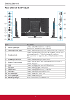
Rear View of the Product
 |
View all ViewSonic CDE3201LED manuals
Add to My Manuals
Save this manual to your list of manuals |
Page 15 highlights
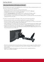
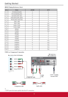
Getting Started Rear View of the Product 8 1 9 2 10 3 11 4 5 6 12 7 Item 1 YPbPr signal input 2 Audio input (left/ right) 3 Earphone Jack 4 SPDIF Optical output 5 Remote Control output 6 USB 7 DC input 8 HDMI input 9 DVI input 10 PC Audio input 11 VGA signal input 12 RS232 signal input Description Connect to the YPbPr output of A/V device. j Composite and Y use the same connector. Connect to the corresponding audio connectors on your A/V device. Connect to earphones. By connecting the earphones, you can listen to the sound from the LCD display through the earphones. j If you connect the earphones, the LCD display speakers will be muted. Connect to the SPDIF input of A/V device. Connect to an IR emitter. This will enable the remote control of external equipment. Connect to USB devices, such as USB flash drive. Connect to the DC input power source. Connect to the HDMI output of A/V devices. Connect to the DVI output of PC devices. Connect to a PC line / audio port. Connect to a PC VGA port. Reserved for the service technician's use. 6
-
 1
1 -
2
-
3
-
4
-
5
-
6
-
7
-
8
-
9
-
 10
10 -
 11
11 -
 12
12 -
 13
13 -
 14
14 -
 15
15 -
 16
16 -
 17
17 -
 18
18 -
 19
19 -
 20
20 -
21
-
22
-
23
-
24
-
25
-
26
-
27
-
28
-
29
-
30
-
31
-
32
-
33
-
34
-
35
-
36
-
37
-
38
-
39
-
40
-
41
-
42
-
43
-
44
-
45
-
46
-
47
-
48
-
49
-
50
 |
 |
