Weider Body Blaster Force 4 Owners Manual - Page 13
Weight Stack Assembly
 |
View all Weider Body Blaster Force 4 manuals
Add to My Manuals
Save this manual to your list of manuals |
Page 13 highlights
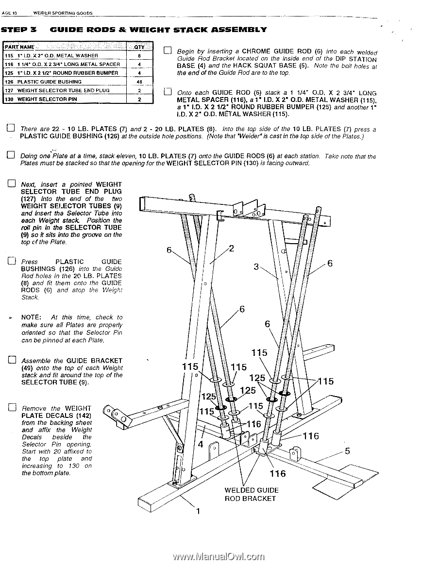
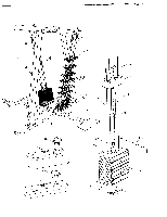
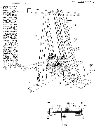
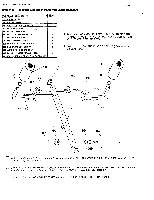
AGE 13 WEIDER SPORTING GOODS STEP 3 GUIDE RODS & WEIGHT STACK ASSEMBLY PART NAME 115 1" I.D. X 2' O.D. METAL WASHER 116 1 1/4" O.D. X 2 314" LONG METAL SPACER 125 1' I.D. X 2 1/2' ROUND RUBBER BUMPER 126 PLASTIC GUIDE BUSHING 127 WEIGHT SELECTOR TUBE END PLUG 130 WEIGHT SELECTOR PIN QTY 8 4 4 48 2 2 I-1 Begin by inserting a CHROME GUIDE ROD (6) into each welded Guide Rod Bracket located on the inside end of the DIP STATION BASE (4) and the HACK SQUAT BASE (5). Note the bolt holes at the end of the Guide Rod are to the top. u Onto each GUIDE ROD (6) stack a 1 1/4" O.D. X 2 3/4" LONG METAL SPACER (116), a 1" I.D. X 2" O.D. METAL WASHER (115), a 1" I.D. X 2 1/2" ROUND RUBBER BUMPER (125) and another 1" I.D. X 2" O.D. METAL WASHER (115). u There are 22 - 10 LB. PLATES (7) and 2 - 20 LB. PLATES (8). Into the top side of the 10 LB. PLATES (7) press a PLASTIC GUIDE BUSHING (126) at the outside hole positions. (Note that 'Weider' is cast in the top side of the Plates.) u Doing onePlate at a time, stack eleven, 10 LB. PLATES (7) onto the GUIDE RODS (6) at each station. Take note that the Plates must be stacked so that the opening for the WEIGHT SELECTOR PIN (130) is facing outward. Next, insert a pointed WEIGHT SELECTOR TUBE END PLUG (127) into the end of the two WEIGHT SELECTOR TUBES (9) and insert the Selector Tube into each Weight stack Position the roll pin in the SELECTOR TUBE (9) so it sits into the groove on the top of the Plate. u Press PLASTIC GUIDE BUSHINGS (126) into the Guide Rod holes in the 20 LB. PLATES (8) and fit them onto the GUIDE RODS (6) and atop the Weight Stack. NOTE: At this time, check to make sure all Plates are properly oriented so that the Selector Pin can be pinned at each Plate. u Assemble the GUIDE BRACKET (49) onto the top of each Weight stack and fit around the top of the SELECTOR TUBE (9). El Remove the WEIGHT PLATE DECALS (142) from the backing sheet and affix the Weight Decals beside the Selector Pin opening. Start with 20 affixed to the top plate and increasing to 130 on the bottom plate. O O 0 O. 2 3 6 6 6 115 125 11 4 0 115 115 125 1 5 115 116 o < 115 116 0 5 116 WELDED GUIDE ROD BRACKET
-
 1
1 -
2
-
3
-
4
-
5
-
6
-
7
-
 8
8 -
 9
9 -
 10
10 -
 11
11 -
 12
12 -
 13
13 -
 14
14 -
 15
15 -
 16
16 -
 17
17 -
 18
18 -
19
-
20
-
21
-
22
-
23
-
24
-
25
-
26
-
27
-
28
-
29
-
30
-
31
-
32
-
33
-
34
-
35
-
36
-
37
-
38
-
39
-
40
-
41
-
42
-
43
-
44
 |
 |