Weider Body Blaster Force 4 Owners Manual - Page 19
Dip Station Asse
 |
View all Weider Body Blaster Force 4 manuals
Add to My Manuals
Save this manual to your list of manuals |
Page 19 highlights
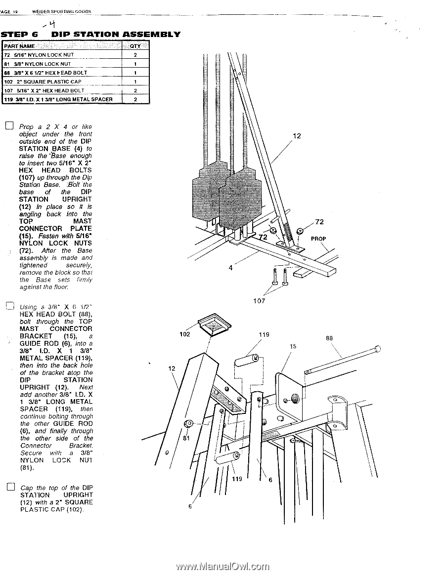
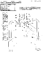
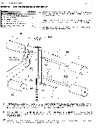
PAGE 19 WEIDER SPORTING GOODS STEP 6 DIP STATION ASSE MBLY PART NAME 72 6/16' NYLON LOCK NUT 81 3/8" NYLON LOCK NUT 88 3/8" X 6 1/2" HEX F-EAD BOLT 102 2" SQUARE PLASTIC CAP 107 5/16' X 2' HEX HEAD BOLT 119 3/8" I.D. X 1 3/8" LONG METAL SPACER QTY 2 1 1 1 2 Prop a 2 X 4 or like object under the front outside end of the DIP STATION BASE (4) to raise the 'Base enough to insert two 5/16" X 2" HEX HEAD BOLTS (107) up through the Dip Station Base. _'Bolt the base of the DIP STATION UPRIGHT (12) in place so it is angling back into the TOP MAST CONNECTOR PLATE (15). Fasten with 5/16" NYLON LOCK NUTS (72). After the Base assembly is made and tightened securely, remove the block so that the Base sets firmly against the floor. Using a 318" X 6 1/2" HEX HEAD BOLT (88), bolt through the TOP MAST CONNECTOR BRACKET (15), a GUIDE ROD (6), into a 3/8" I.D. X 1 3/8" METAL SPACER (119), then into the back hole of the bracket atop the DIP STATION UPRIGHT (12). Next add another 3/8" I.D. X 1 3/8' LONG METAL SPACER (119), then continue bolting through the other GUIDE ROD (6), and finally through the other side of the Connector Bracket. Secure with a 3/8" NYLON LOCK NUT (81). Cap the top of the DIP STATION UPRIGHT (12) with a 2" SQUARE PLASTIC CAP (102). 12 4s. vw 4 72 0 PROP 107 102 12 119 88 15 Qr. L 81 II 119 6 6
-
 1
1 -
2
-
3
-
4
-
5
-
6
-
7
-
8
-
9
-
10
-
11
-
12
-
13
-
 14
14 -
 15
15 -
 16
16 -
 17
17 -
 18
18 -
 19
19 -
 20
20 -
 21
21 -
 22
22 -
 23
23 -
 24
24 -
25
-
26
-
27
-
28
-
29
-
30
-
31
-
32
-
33
-
34
-
35
-
36
-
37
-
38
-
39
-
40
-
41
-
42
-
43
-
44
 |
 |