Weider Body Blaster Force 4 Owners Manual - Page 25
Pulley, Nylon, Washer, Round, Screw, Metal, Spacer, Press, Station
 |
View all Weider Body Blaster Force 4 manuals
Add to My Manuals
Save this manual to your list of manuals |
Page 25 highlights
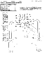
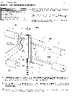
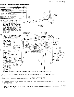
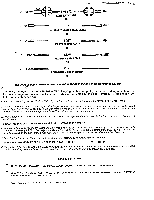
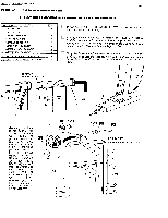
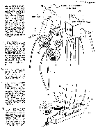
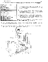
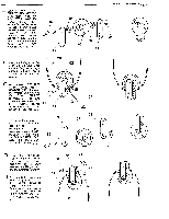
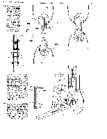
kGE 25 WEIDER SPORTING GOODS STEP 10 CABLE ASSEMBLIES 1. LAT PULL -DOWN & LOWER PULLEY ASSEMBLY PART NAME 61 4 1/2' PULLEY 62 31/2" PULLEY QTY 1 Select the 174 1/2" LONG LAT CABLE (28) (has two stopper balls and one adjuster sleeve on it). 3 67 1/4' NYLON LOCK NUT ! 80 3/8' FLAT WASHER 81 3/8" NYLON LOCK NUT 91 3/8" X 4" HEX HEAD BOLT 92 3/8- X 2 3/4" HEX HEAD BOLT 1 4 Starting from the front of the Top Mast ARM PRESS STATION (3), feed the Cable end with the stopper ball and adjuster ferrule into the 4 end of the Top Mast and pull it out through the slot in the bottom 1 center of the Top Frames where the Top Mast joins. 2 93 3/8" X 2' HEX HEAD BOLT 1 u Bring the Cable through between the GUIDE RODS (6) on the DIP i 99 1/4' X 21/4" ROUND HEAD SCREW 1 120 3/8" I.D. X 1/2'`L.ONG METAL SPACER 6 STATION UPRIGHT (12) and feed the Cable end with the ball and ferrule through the slot in the bottom of the DIP STATION UPRIGHT (12). TOP MAST ARM PRESS STATION 12 28 3 6 26 u Returning now back 80 81 051 to the front of the Top Mast, select a 4 1/2" PULLEY (A) (61) and position the 28 Cable in the Pulley groove. Fit a 3/8" FLAT WASHER (80) and a 3/8" I.D. X 1/2' LONG METAL SPACER (120) onto a 3/8" X 2 61 3/4" HEX HEAD BOLT (92) and bolt into Top Frame and the Pulley. Slide another 1/2" LONG 26 SPACER (120) and 3/8" FLAT WASHER (80) onto the bolt and secure with a 3/8" NYLON LOCK NUT (81). 0 4 28 O 120 c( 80 90 2 TOP MAST ARM PRESS STATION 3 26 0 0
-
 1
1 -
2
-
3
-
4
-
5
-
6
-
7
-
8
-
9
-
10
-
11
-
12
-
13
-
14
-
15
-
16
-
17
-
18
-
19
-
 20
20 -
 21
21 -
 22
22 -
 23
23 -
 24
24 -
 25
25 -
 26
26 -
 27
27 -
 28
28 -
 29
29 -
 30
30 -
31
-
32
-
33
-
34
-
35
-
36
-
37
-
38
-
39
-
40
-
41
-
42
-
43
-
44
 |
 |
