Weider Body Blaster Force 4 Owners Manual - Page 39
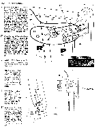
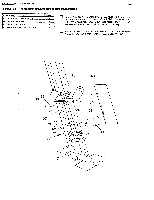
Ii:i:k:x:i, Washer, Nylon, Round, Screw, Plastic, Insert, Square, Spacer
 |
View all Weider Body Blaster Force 4 manuals
Add to My Manuals
Save this manual to your list of manuals |
Page 39 highlights
STEP 11 COMPLETING DIP STATION PAGE 38 WEIDER SPORTING GOODS PART NAME :Ii:i:K:x:i:: *i:: ::;;;;I 66 1/4" FLAT WASHER 71 5/16" FLAT WASHER 72 5/16' NYLON LOCK NUT 74 5/16' X 2 1/4' HEX HEAD BOLT 76 5/16' X 2 3/4' HEX HEAD BOLT 98 1/4" X 21/2" ROUND HEAD SCREW 99 1/4' X 21/4' ROUND HEAD SCREW 105 1" ROUND PLASTIC INSERT CAP I106 1 3/4' SQUARE PLASTIC INSERT CAP 124 5t16' I.D. X 7/16' LONG SPACER QTY 6 4 4 2 2 2 4 2 2 2 Attach a FOREARM PAD (36) to each of the Dipping Arms with 1/4" X 2 1/4" ROUND HEAD SCREWS (99) and 1/4" FLAT WASHERS (66). 98 66 36 Bolt a DIP HANDLE (37) into the forward ends of the Dipping Arms. Place a 5/16" FLAT WASHER (71) and a 5/16" I.D. X 7/16" LONG SPACER (124) onto a 5/16" X 2 1/4" HEX HEAD BOLT (74) and bolt through the Dip Handle assembly. Secure with another 5/16" FLAT WASHER (71) and a 5/1'6' NYLON LOCK NUT (72). 76 46 76 c=,=vio 98 66 El Attach the DIPPING ARMS - RIGHT (46) and LEFT (47) to the DIP STATION UPRIGHT (12) using 5/16' X 2 3/4" HEX HEAD BOLTS (76) and 5/16" NYLON LOCK NUTS (72). Cap the ends with 1 3/4" SQUARE PLASTIC INSERT CAPS (106). [1] Fasten the DIP STATION BACK PAD (35) to the UPRIGHT (12) by bolting through from the Frame into the Pad with 1/4" X 2 1/2" ROUND HEAD SCREWS (98) and1/4" FLAT WASHERS (66). 10 38 35 0 37 ~4--- 71 -o -o ,-106 36 71 66 72 66 47 66 99 99 12 Press a 1" ROUND PLASTIC INSERT CAP (105) into the top end of the Dip Handles and slide a 1" I.D. X 5" FOAM GRIP (38) on each Handle. 4
-
 1
1 -
2
-
3
-
4
-
5
-
6
-
7
-
8
-
9
-
10
-
11
-
12
-
13
-
14
-
15
-
16
-
17
-
18
-
19
-
20
-
21
-
22
-
23
-
24
-
25
-
26
-
27
-
28
-
29
-
30
-
31
-
32
-
33
-
 34
34 -
 35
35 -
 36
36 -
 37
37 -
 38
38 -
 39
39 -
 40
40 -
 41
41 -
 42
42 -
 43
43 -
 44
44
 |
 |
