Weider Body Blaster Force 4 Owners Manual - Page 28
Weider Body Blaster Force 4 Manual
 |
View all Weider Body Blaster Force 4 manuals
Add to My Manuals
Save this manual to your list of manuals |
Page 28 highlights
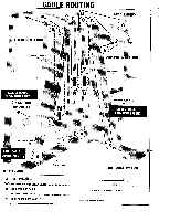
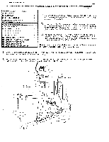
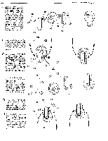
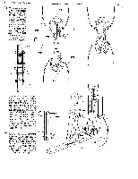
Choose two DUAL PULLEY CONNECTOR BRACKETS (51) and with a 3/8" X 1 3/4" HEX HEAD BOLT (93) assemble one Connector Bracket, a 3/8" FLAT WASHER (80), a 3 1/2" PULLEY (G) (62), another 3/8" FLAT WASHER (80), and the other Connector Bracket. Fasten with a 3/8" NYLON LOCK NUT (81). 80 82 O 0 62 ° 51 PAGE 28 WEIDER SPORTING GOODS (3) 0 81 0 0 51 Hang this Pulley assembly over the top LAT BAR CABLE (28) as it loops between the two Pulleys at the top of the Dip Station. 28 62 Next position a 3/8' I.D. X 1 1/4" LONG METAL SPACER (122) between the middle. Bolt holes in the DUAL PULLEY BRACKETS (51) and assemble with a 1/4' X 1 3/4" ROUND HEAD 68 SCREW (68) and a 1/4" NYLON LOCK NUT (67). 0 51 u To a second pair of DUAL PULLEY CONNECTOR BRACKETS (51) assemble another 3 1/2" PULLEY (H) (62) with a 3/8" X 1 3/4" HEX HEAD BOLT (82) and a 3/8" NYLON LOCK NUT (81). 51 82 0 67 122 51 62 N r-() 0 O 81 u Loop the PEC-DECK WEIGHT STACK CABLE (29) over this Pulley assembly as it runs between the Weight stack and the dual Base Pulleys. Li Trap the Cable within the Brackets by bolting a 3/8" X 1' METAL SPACER (123) between the Connector Brackets with a 1/4" X 1 3/4" ROUND HEAD SCREW (68) and 1/4" NYLON LOCK NUT (67). 51 123 68 0 67 29 62 O 0 O O
-
 1
1 -
2
-
3
-
4
-
5
-
6
-
7
-
8
-
9
-
10
-
11
-
12
-
13
-
14
-
15
-
16
-
17
-
18
-
19
-
20
-
21
-
22
-
 23
23 -
 24
24 -
 25
25 -
 26
26 -
 27
27 -
 28
28 -
 29
29 -
 30
30 -
 31
31 -
 32
32 -
 33
33 -
34
-
35
-
36
-
37
-
38
-
39
-
40
-
41
-
42
-
43
-
44
 |
 |
