Weider Body Blaster Force 4 Owners Manual - Page 26
Station, Finger, Tighten
 |
View all Weider Body Blaster Force 4 manuals
Add to My Manuals
Save this manual to your list of manuals |
Page 26 highlights
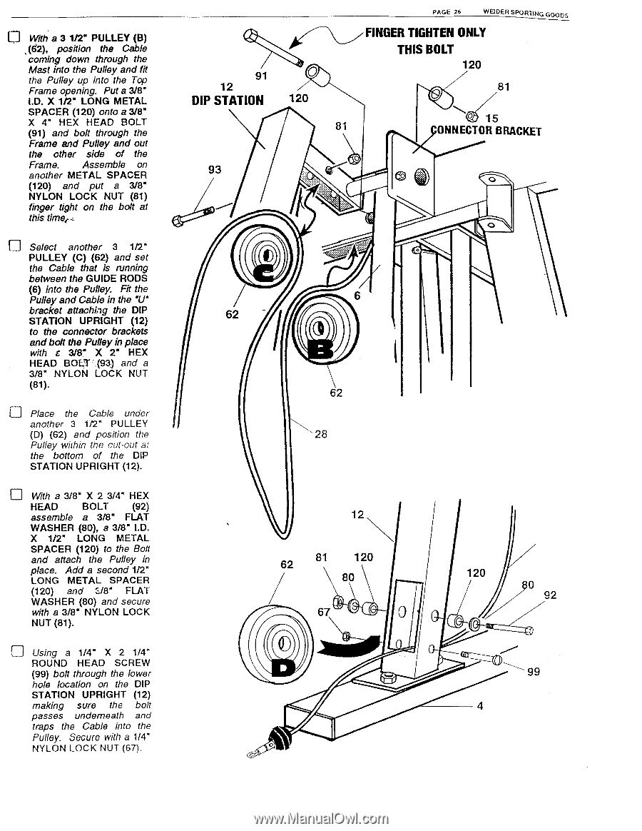
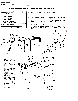
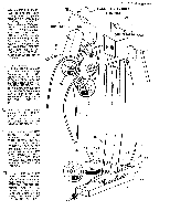
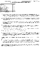
With a 3 1/2" PULLEY (B) ,(62), position the Cable coming down through the Mast into the Pulley and fit the Pulley up into the Top Frame opening. Put a 3/8" I.D. X 1/2" LONG METAL SPACER (120) onto a 3/8" X 4" HEX HEAD BOLT (91) and bolt through the Frame and Pulley and out the other side of the Frame. Assemble on another METAL SPACER (120) and put a 3/8" NYLON LOCK NUT (81) finger tight on the bolt at this time,- Select another 3 1/2" PULLEY (C) (62) and set the Cable that is running between the GUIDE RODS (6) into the Pulley. Fit the Pulley and Cable in the V' bracket attaching the DIP STATION UPRIGHT (12) to the connector brackets and bolt the Pulley in place with c 3/8" X 2" HEX HEAD BOLT (93) and a 3/8" NYLON LOCK NUT (81). El Place the Cable under another 3 1/2" PULLEY (D) (62) and position the Pulley within the cut-out at the bottom of the DIP STATION UPRIGHT (12). I_J With a 3/8" X 2 3/4" HEX HEAD BOLT (92) assemble a 3/8" FLAT WASHER (80), a 3/8" I.D. X 1/2" LONG METAL SPACER (120) to the Bolt and attach the Pulley in place. Add a second 1/2" LONG METAL SPACER (120) and :";/8" FLAT WASHER (80) and secure with a 3/8" NYLON LOCK NUT (81). Using a 1/4" X 2 1/4" ROUND HEAD SCREW (99) bolt through the lower hole location on the DIP STATION UPRIGHT (12) making sure the bolt passes underneath and traps the Cable into the Pulley. Secure with a 1/4" NYLON LOCK NUT (67). 91 12 DIP STATION 120 PAGE 26 WEIDER SPORTING GOODS FINGER TIGHTEN ONLY THIS BOLT 120 81 0 15 81 ONNECTOR BRACKET 93 0 0 ff.:#1.-.; 6 62 3 62 28 12 81 62 120 80 67 0 0 120 0 92 99 4
-
 1
1 -
2
-
3
-
4
-
5
-
6
-
7
-
8
-
9
-
10
-
11
-
12
-
13
-
14
-
15
-
16
-
17
-
18
-
19
-
20
-
 21
21 -
 22
22 -
 23
23 -
 24
24 -
 25
25 -
 26
26 -
 27
27 -
 28
28 -
 29
29 -
 30
30 -
 31
31 -
32
-
33
-
34
-
35
-
36
-
37
-
38
-
39
-
40
-
41
-
42
-
43
-
44
 |
 |