ZyXEL MES3500-24F User Guide - Page 198
MVR Configuration Example
 |
View all ZyXEL MES3500-24F manuals
Add to My Manuals
Save this manual to your list of manuals |
Page 198 highlights
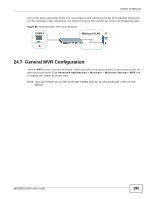
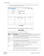
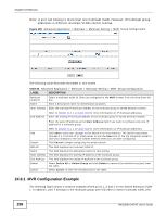
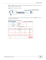
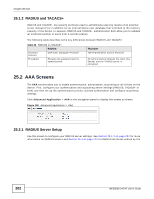
Chapter 24 Multicast Note: A port can belong to more than one multicast VLAN. However, IP multicast group addresses in different multicast VLANs cannot overlap. Figure 100 Advanced Application > Multicast > Multicast Setting > MVR: Group Configuration The following table describes the labels in this screen. Table 65 Advanced Application > Multicast > Multicast Setting > MVR: Group Configuration LABEL Multicast VLAN ID Name Start Address DESCRIPTION Select a multicast VLAN ID (that you configured in the MVR screen) from the drop-down list box. Enter a descriptive name for identification purposes. Enter the starting IP multicast address of the multicast group in dotted decimal notation. End Address Refer to Section 24.1.1 on page 186 for more information on IP multicast addresses. Enter the ending IP multicast address of the multicast group in dotted decimal notation. Enter the same IP address as the Start Address field if you want to configure only one IP address for a multicast group. Add Cancel MVLAN Name Start Address End Address Delete Cancel Refer to Section 24.1.1 on page 186 for more information on IP multicast addresses. Click Add to save your changes to the Switch's run-time memory. The Switch loses these changes if it is turned off or loses power, so use the Save link on the top navigation panel to save your changes to the non-volatile memory when you are done configuring. Click Cancel to begin configuring this screen afresh. This field displays the multicast VLAN ID. This field displays the descriptive name for this setting. This field displays the starting IP address of the multicast group. This field displays the ending IP address of the multicast group. Select Delete All or Delete Group and click Delete to remove the selected entry(ies) from the table. Select Cancel to clear the checkbox(es) in the table. 24.8.1 MVR Configuration Example The following figure shows a network example where ports 1, 2 and 3 on the Switch belong to VLAN 1. In addition, port 7 belongs to the multicast group with VID 200 to receive multicast traffic (the 198 MES3500-24/24F User's Guide
-
 1
1 -
2
-
3
-
4
-
5
-
6
-
7
-
8
-
9
-
10
-
11
-
12
-
13
-
14
-
15
-
16
-
17
-
18
-
19
-
20
-
21
-
22
-
23
-
24
-
25
-
26
-
27
-
28
-
29
-
30
-
31
-
32
-
33
-
34
-
35
-
36
-
37
-
38
-
39
-
40
-
41
-
42
-
43
-
44
-
45
-
46
-
47
-
48
-
49
-
50
-
51
-
52
-
53
-
54
-
55
-
56
-
57
-
58
-
59
-
60
-
61
-
62
-
63
-
64
-
65
-
66
-
67
-
68
-
69
-
70
-
71
-
72
-
73
-
74
-
75
-
76
-
77
-
78
-
79
-
80
-
81
-
82
-
83
-
84
-
85
-
86
-
87
-
88
-
89
-
90
-
91
-
92
-
93
-
94
-
95
-
96
-
97
-
98
-
99
-
100
-
101
-
102
-
103
-
104
-
105
-
106
-
107
-
108
-
109
-
110
-
111
-
112
-
113
-
114
-
115
-
116
-
117
-
118
-
119
-
120
-
121
-
122
-
123
-
124
-
125
-
126
-
127
-
128
-
129
-
130
-
131
-
132
-
133
-
134
-
135
-
136
-
137
-
138
-
139
-
140
-
141
-
142
-
143
-
144
-
145
-
146
-
147
-
148
-
149
-
150
-
151
-
152
-
153
-
154
-
155
-
156
-
157
-
158
-
159
-
160
-
161
-
162
-
163
-
164
-
165
-
166
-
167
-
168
-
169
-
170
-
171
-
172
-
173
-
174
-
175
-
176
-
177
-
178
-
179
-
180
-
181
-
182
-
183
-
184
-
185
-
186
-
187
-
188
-
189
-
190
-
191
-
192
-
 193
193 -
 194
194 -
 195
195 -
 196
196 -
 197
197 -
 198
198 -
 199
199 -
 200
200 -
 201
201 -
 202
202 -
 203
203 -
204
-
205
-
206
-
207
-
208
-
209
-
210
-
211
-
212
-
213
-
214
-
215
-
216
-
217
-
218
-
219
-
220
-
221
-
222
-
223
-
224
-
225
-
226
-
227
-
228
-
229
-
230
-
231
-
232
-
233
-
234
-
235
-
236
-
237
-
238
-
239
-
240
-
241
-
242
-
243
-
244
-
245
-
246
-
247
-
248
-
249
-
250
-
251
-
252
-
253
-
254
-
255
-
256
-
257
-
258
-
259
-
260
-
261
-
262
-
263
-
264
-
265
-
266
-
267
-
268
-
269
-
270
-
271
-
272
-
273
-
274
-
275
-
276
-
277
-
278
-
279
-
280
-
281
-
282
-
283
-
284
-
285
-
286
-
287
-
288
-
289
-
290
-
291
-
292
-
293
-
294
-
295
-
296
-
297
-
298
-
299
-
300
-
301
-
302
-
303
-
304
-
305
-
306
-
307
-
308
-
309
-
310
-
311
-
312
-
313
-
314
-
315
-
316
-
317
-
318
-
319
-
320
-
321
-
322
-
323
-
324
-
325
-
326
-
327
-
328
-
329
-
330
-
331
-
332
-
333
-
334
-
335
-
336
-
337
-
338
-
339
-
340
-
341
-
342
-
343
-
344
-
345
-
346
-
347
-
348
-
349
 |
 |
