ZyXEL MES3500-24F User Guide - Page 37
Pin Assignments
 |
View all ZyXEL MES3500-24F manuals
Add to My Manuals
Save this manual to your list of manuals |
Page 37 highlights
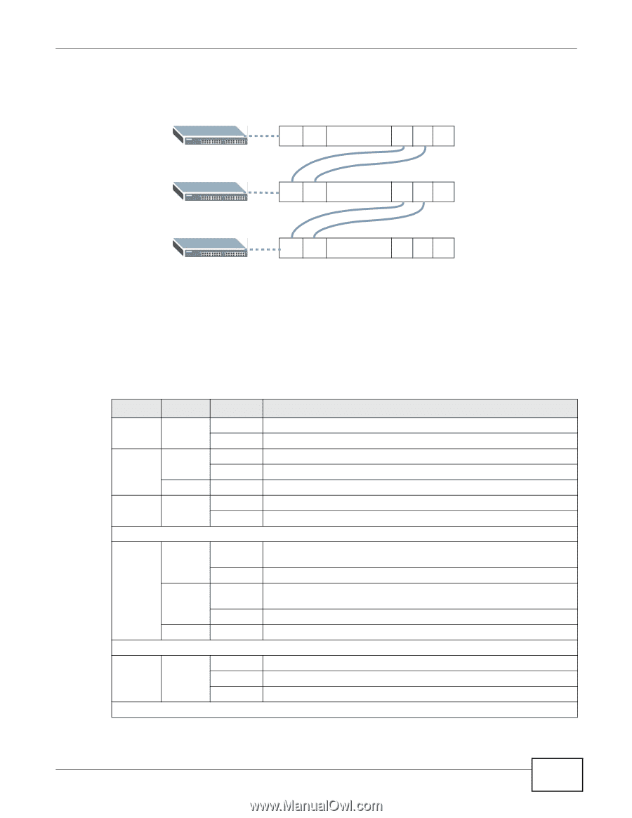
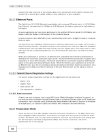
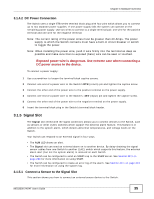
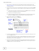
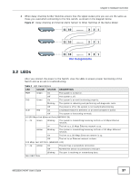
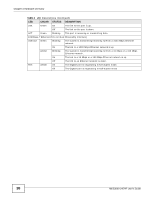
Chapter 3 Hardware Overview 2 When daisy-chaining further Switches ensure that the signal output pins you use are the same as those you used when connecting to the first switch, as shown in the diagram below. Figure 17 Daisy-chaining an External Alarm Sensor to Other Switches of the Same Model 11 10 ......... 3 2 1 11 10 ......... 3 2 1 11 10 ......... 3 2 1 Pin Assignments 3.2 LEDs After you connect the power to the Switch, view the LEDs to ensure proper functioning of the Switch and as an aid in troubleshooting. Table 2 LED Descriptions LED COLOR STATUS DESCRIPTION PWR Green On The system is turned on. Off The system is off. SYS Green On The system is on and functioning properly. Blinking The system is rebooting and performing self-diagnostic tests. Off The power is off or the system is not ready/malfunctioning. ALM Red On A hardware failure is detected, or an external alarm is active. Off The system is functioning normally. 10/100 Mbps Fast Ethernet Ports (MES3500-24) 1 ~ 24 Green Blinking The system is transmitting/receiving to/from a 10 Mbps Ethernet network. on The link to a 10 Mbps Ethernet network is up. Amber Blinking The system is transmitting/receiving to/from a 100 Mbps Ethernet network. On The link to a 100 Mbps Ethernet network is up. Off The link to an Ethernet network is down. 100 Mbps Fast SFP Ports (MES3500-24F) 1 ~ 24 Amber On The port has a successfule connection. Off No Ethernet device is connected to this port. Blinking This port is receiving or transmitting data. Mini-GBIC Slots MES3500-24/24F User's Guide 37
-
 1
1 -
2
-
3
-
4
-
5
-
6
-
7
-
8
-
9
-
10
-
11
-
12
-
13
-
14
-
15
-
16
-
17
-
18
-
19
-
20
-
21
-
22
-
23
-
24
-
25
-
26
-
27
-
28
-
29
-
30
-
31
-
 32
32 -
 33
33 -
 34
34 -
 35
35 -
 36
36 -
 37
37 -
 38
38 -
 39
39 -
 40
40 -
 41
41 -
 42
42 -
43
-
44
-
45
-
46
-
47
-
48
-
49
-
50
-
51
-
52
-
53
-
54
-
55
-
56
-
57
-
58
-
59
-
60
-
61
-
62
-
63
-
64
-
65
-
66
-
67
-
68
-
69
-
70
-
71
-
72
-
73
-
74
-
75
-
76
-
77
-
78
-
79
-
80
-
81
-
82
-
83
-
84
-
85
-
86
-
87
-
88
-
89
-
90
-
91
-
92
-
93
-
94
-
95
-
96
-
97
-
98
-
99
-
100
-
101
-
102
-
103
-
104
-
105
-
106
-
107
-
108
-
109
-
110
-
111
-
112
-
113
-
114
-
115
-
116
-
117
-
118
-
119
-
120
-
121
-
122
-
123
-
124
-
125
-
126
-
127
-
128
-
129
-
130
-
131
-
132
-
133
-
134
-
135
-
136
-
137
-
138
-
139
-
140
-
141
-
142
-
143
-
144
-
145
-
146
-
147
-
148
-
149
-
150
-
151
-
152
-
153
-
154
-
155
-
156
-
157
-
158
-
159
-
160
-
161
-
162
-
163
-
164
-
165
-
166
-
167
-
168
-
169
-
170
-
171
-
172
-
173
-
174
-
175
-
176
-
177
-
178
-
179
-
180
-
181
-
182
-
183
-
184
-
185
-
186
-
187
-
188
-
189
-
190
-
191
-
192
-
193
-
194
-
195
-
196
-
197
-
198
-
199
-
200
-
201
-
202
-
203
-
204
-
205
-
206
-
207
-
208
-
209
-
210
-
211
-
212
-
213
-
214
-
215
-
216
-
217
-
218
-
219
-
220
-
221
-
222
-
223
-
224
-
225
-
226
-
227
-
228
-
229
-
230
-
231
-
232
-
233
-
234
-
235
-
236
-
237
-
238
-
239
-
240
-
241
-
242
-
243
-
244
-
245
-
246
-
247
-
248
-
249
-
250
-
251
-
252
-
253
-
254
-
255
-
256
-
257
-
258
-
259
-
260
-
261
-
262
-
263
-
264
-
265
-
266
-
267
-
268
-
269
-
270
-
271
-
272
-
273
-
274
-
275
-
276
-
277
-
278
-
279
-
280
-
281
-
282
-
283
-
284
-
285
-
286
-
287
-
288
-
289
-
290
-
291
-
292
-
293
-
294
-
295
-
296
-
297
-
298
-
299
-
300
-
301
-
302
-
303
-
304
-
305
-
306
-
307
-
308
-
309
-
310
-
311
-
312
-
313
-
314
-
315
-
316
-
317
-
318
-
319
-
320
-
321
-
322
-
323
-
324
-
325
-
326
-
327
-
328
-
329
-
330
-
331
-
332
-
333
-
334
-
335
-
336
-
337
-
338
-
339
-
340
-
341
-
342
-
343
-
344
-
345
-
346
-
347
-
348
-
349
 |
 |