Asus A8R-MVP A8R-MVP User's Manual for English Edtion - Page 26
Layout Contents - no audio
 |
View all Asus A8R-MVP manuals
Add to My Manuals
Save this manual to your list of manuals |
Page 26 highlights
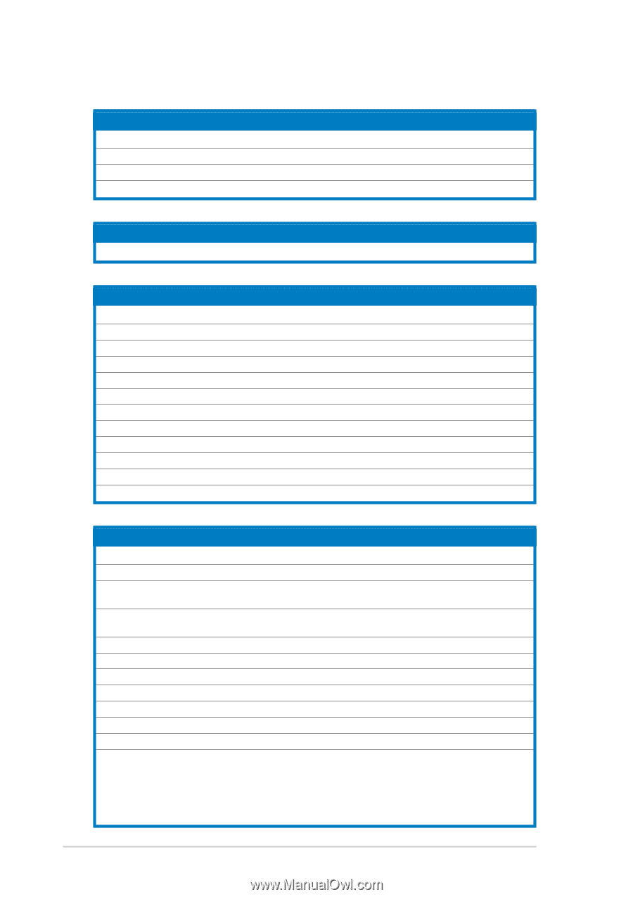
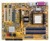
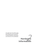
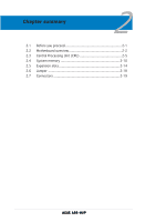
2.2.4 Layout Contents Slots 1. DDR DIMM slots 2. PCI slots 3. PCI Express x1 slot 4. PCI Express x16 slots Page 2-10 2-16 2-16 2-16 Jumper 1. Clear RTC RAM (3-pin CLRTC) Page 2-18 Rear panel connectors 1. PS/2 mouse port 2. Parallel port 3. IEEE 1394a port 4. LAN (RJ-45) port 5. Line In port 6. Line Out port 7. Microphone port 8. USB 2.0 ports 3 and 4 9. USB 2.0 ports 1 and 2 10. Serial port 11. Coaxial S/PDIF Out port 12. PS/2 keyboard port Page 2-19 2-19 2-19 2-19 2-19 2-19 2-19 2-20 2-20 2-20 2-20 2-20 Internal connectors 1. Floppy disk drive connector (34-1 pin FLOPPY) 2. IDE connectors (40-1 pin PRI_IDE, 40-1 pin SEC_IDE) 3. Serial ATA connectors (7-pin SATA1 [red], SATA2 [red], SATA3 [black], SATA4 [black]) 4. CPU, Chassis, and Power fan connectors (3-pin CPU_FAN, 3-pin CHA_FAN, 3-pin PWR_FAN ) 5. USB connectors (10-1 USB56, USB78_WFG) 6. Power connectors (24-pin EATXPWR, 4-pin ATX12V; 4-pin EZ_PLUG) 7. GAME/MIDI port connector (16-1 pin GAME) 8. IEEE 1394a connector (10-1 pin IE1394_1) 9. Chassis intrusion connector (4-1 pin CHASSIS) 10. Front panel audio connector (10-1 pin AAFP) 11. Internal audio connectors (4-pin CD [black], 4-pin AUX [white]) 12. System panel connectors (20 pin PANEL) - System Power LED (Green 3-pin PLED) - Hard Disk activity (Red 2-pin IDE_LED) - System warning speaker (Orange 4-pin SPEAKER) - Power/Soft-off button(Yellow 2-pin PWRSW) - Reset switch (Blue 2-pin RESET) Page 2-21 2-21 2-22 2-23 2-24 2-24 2-25 2-26 2-26 2-27 2-27 2-28 2-4 Chapter 2: Hardware information
-
 1
1 -
2
-
3
-
4
-
5
-
6
-
7
-
8
-
9
-
10
-
11
-
12
-
13
-
14
-
15
-
16
-
17
-
18
-
19
-
20
-
 21
21 -
 22
22 -
 23
23 -
 24
24 -
 25
25 -
 26
26 -
 27
27 -
 28
28 -
 29
29 -
 30
30 -
 31
31 -
32
-
33
-
34
-
35
-
36
-
37
-
38
-
39
-
40
-
41
-
42
-
43
-
44
-
45
-
46
-
47
-
48
-
49
-
50
-
51
-
52
-
53
-
54
-
55
-
56
-
57
-
58
-
59
-
60
-
61
-
62
-
63
-
64
-
65
-
66
-
67
-
68
-
69
-
70
-
71
-
72
-
73
-
74
-
75
-
76
-
77
-
78
-
79
-
80
-
81
-
82
-
83
-
84
-
85
-
86
-
87
-
88
-
89
-
90
-
91
-
92
-
93
-
94
-
95
-
96
-
97
-
98
-
99
-
100
-
101
-
102
-
103
-
104
-
105
-
106
-
107
-
108
-
109
-
110
-
111
-
112
-
113
-
114
-
115
-
116
-
117
-
118
-
119
-
120
-
121
-
122
-
123
-
124
-
125
-
126
-
127
-
128
-
129
-
130
-
131
-
132
-
133
-
134
-
135
-
136
-
137
-
138
-
139
-
140
-
141
-
142
-
143
-
144
-
145
-
146
-
147
-
148
-
149
-
150
 |
 |