Asus A8R-MVP A8R-MVP User's Manual for English Edtion - Page 44
RAID 0, RAID 1, RAID 0+1, RAID 5, and JBOD configuration. Refer - sata
 |
View all Asus A8R-MVP manuals
Add to My Manuals
Save this manual to your list of manuals |
Page 44 highlights
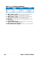
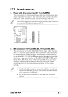
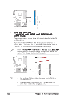
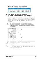
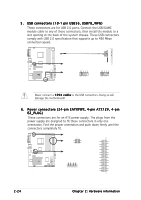
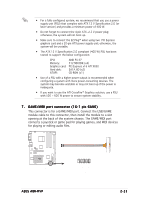
NOTE: Orient the red markings (usually zigzag) on the IDE ribbon cable to PIN 1. PRI_IDE SEC_IDE A8R-MVP ® A8R-MVP IDE connectors PIN 1 3. Serial ATA connectors (7-pin SATA1 [red], SATA2 [red], SATA3 [black], SATA4 [black]) These connectors are for the Serial ATA signal cables for Serial ATA hard disk drives. If you installed Serial ATA hard disk drives, you can can create a RAID 0, RAID 1, RAID 0+1, RAID 5, and JBOD configuration. Refer to Chapter 5 for information on creating a RAID configuration. Enable the S e r i a l A T A C o n t r o l l e r and O n b o a r d S A T A B o o t R O M items in the BIOS if you want to use the Serial ATA RAID feature. See section "4.3.5 Storage Configuration" for details. A8R-MVP ® SATA4 GND RSATA_TXP4 RSATA_TXN4 GND RSATA_RXP4 RSATA_RXN4 GND A8R-MVP SATA connectors SATA2 GND RSATA_TXP2 RSATA_TXN2 GND RSATA_RXP2 RSATA_RXN2 GND SATA3 GND RSATA_TXP3 RSATA_TXN3 GND RSATA_RXP3 RSATA_RXN3 GND SATA1 GND RSATA_TXP1 RSATA_TXN1 GND RSATA_RXP1 RSATA_RXN1 GND • Plug your Serial ATA boot disk on the master port (SATA1/2 to support S3 function). • Install the Windows® 2000 Service Pack 4 or the Windows® XP Service Pack1 or later when using Serial ATA. 2-22 Chapter 2: Hardware information
-
 1
1 -
2
-
3
-
4
-
5
-
6
-
7
-
8
-
9
-
10
-
11
-
12
-
13
-
14
-
15
-
16
-
17
-
18
-
19
-
20
-
21
-
22
-
23
-
24
-
25
-
26
-
27
-
28
-
29
-
30
-
31
-
32
-
33
-
34
-
35
-
36
-
37
-
38
-
 39
39 -
 40
40 -
 41
41 -
 42
42 -
 43
43 -
 44
44 -
 45
45 -
 46
46 -
 47
47 -
 48
48 -
 49
49 -
50
-
51
-
52
-
53
-
54
-
55
-
56
-
57
-
58
-
59
-
60
-
61
-
62
-
63
-
64
-
65
-
66
-
67
-
68
-
69
-
70
-
71
-
72
-
73
-
74
-
75
-
76
-
77
-
78
-
79
-
80
-
81
-
82
-
83
-
84
-
85
-
86
-
87
-
88
-
89
-
90
-
91
-
92
-
93
-
94
-
95
-
96
-
97
-
98
-
99
-
100
-
101
-
102
-
103
-
104
-
105
-
106
-
107
-
108
-
109
-
110
-
111
-
112
-
113
-
114
-
115
-
116
-
117
-
118
-
119
-
120
-
121
-
122
-
123
-
124
-
125
-
126
-
127
-
128
-
129
-
130
-
131
-
132
-
133
-
134
-
135
-
136
-
137
-
138
-
139
-
140
-
141
-
142
-
143
-
144
-
145
-
146
-
147
-
148
-
149
-
150
 |
 |
