Asus A8R-MVP A8R-MVP User's Manual for English Edtion - Page 46
USB connectors 10-1 pin USB56, USB78_WFG
 |
View all Asus A8R-MVP manuals
Add to My Manuals
Save this manual to your list of manuals |
Page 46 highlights
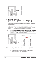
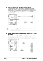
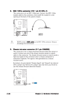
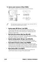
5 . USB connectors (10-1 pin USB56, USB78_WFG) These connectors are for USB 2.0 ports. Connect the USB/GAME module cable to any of these connectors, then install the module to a slot opening at the back of the system chassis. These USB connectors comply with USB 2.0 specification that supports up to 480 Mbps connection speed. USB+5V USB_P6USB_P6+ GND NC USB+5V USB_P8USB_P8+ GND NC A8R-MVP ® USB78_WFG 1 A8R-MVP USB 2.0 connectors USB56 1 USB+5V USB_P5USB_P5+ GND USB+5V USB_P7USB_P7+ GND Never connect a 1 3 9 4 c a b l e to the USB connectors. Doing so will damage the motherboard! 6 . Power connectors (24-pin EATXPWR, 4-pin ATX12V, 4-pin EZ_PLUG) These connectors are for an ATX power supply. The plugs from the power supply are designed to fit these connectors in only one orientation. Find the proper orientation and push down firmly until the connectors completely fit. ATX12V EATXPWR +12V DC GND +5V EZ_DET GND +12V A8R-MVP ® EZ_PLUG A8R-MVP ATX power connectors +12V DC +3 Volts GND +12 Volts +12 Volts +5V Standby Power OK Ground +5 Volts Ground +5 Volts Ground +3 Volts +3 Volts Ground +5 Volts +5 Volts +5 Volts -5 Volts Ground Ground Ground PSON# Ground -12 Volts +3 Volts 2-24 Chapter 2: Hardware information
-
 1
1 -
2
-
3
-
4
-
5
-
6
-
7
-
8
-
9
-
10
-
11
-
12
-
13
-
14
-
15
-
16
-
17
-
18
-
19
-
20
-
21
-
22
-
23
-
24
-
25
-
26
-
27
-
28
-
29
-
30
-
31
-
32
-
33
-
34
-
35
-
36
-
37
-
38
-
39
-
40
-
 41
41 -
 42
42 -
 43
43 -
 44
44 -
 45
45 -
 46
46 -
 47
47 -
 48
48 -
 49
49 -
 50
50 -
 51
51 -
52
-
53
-
54
-
55
-
56
-
57
-
58
-
59
-
60
-
61
-
62
-
63
-
64
-
65
-
66
-
67
-
68
-
69
-
70
-
71
-
72
-
73
-
74
-
75
-
76
-
77
-
78
-
79
-
80
-
81
-
82
-
83
-
84
-
85
-
86
-
87
-
88
-
89
-
90
-
91
-
92
-
93
-
94
-
95
-
96
-
97
-
98
-
99
-
100
-
101
-
102
-
103
-
104
-
105
-
106
-
107
-
108
-
109
-
110
-
111
-
112
-
113
-
114
-
115
-
116
-
117
-
118
-
119
-
120
-
121
-
122
-
123
-
124
-
125
-
126
-
127
-
128
-
129
-
130
-
131
-
132
-
133
-
134
-
135
-
136
-
137
-
138
-
139
-
140
-
141
-
142
-
143
-
144
-
145
-
146
-
147
-
148
-
149
-
150
 |
 |
