Behringer 2600 GRAY MEANIE Quick Start Guide - Page 5
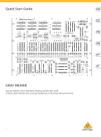
GRAY MEANIE Controls
 |
View all Behringer 2600 GRAY MEANIE manuals
Add to My Manuals
Save this manual to your list of manuals |
Page 5 highlights
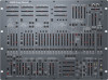
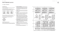
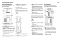
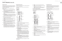
8 GRAY MEANIE GRAY MEANIE Controls (EN) Step 1: Controls Pre-Wired Connections (1) INITIAL OSCILLATOR FREQUENCY - This slider chooses a VCO's coarse (1) The panel silk-screening displays the various connections between modules that have been pre-wired at the factory. operating frequency in four ranges for audio (10 Hz, 100 Hz, 1 kHz or 10 kHz) or four sub-audio frequency ranges (.03 Hz, .3 Hz, 3.0 Hz or 30 Hz) when the VCO operates as a Low Frequency Oscillator (LFO). To choose For example, in the VOLTAGE CONTROLLED FILTER/RESONATOR VCF section, between audio and LFO modes, use the AUDIO/LF sliding switch in the pre-wired connections from Voltage Controlled Oscillators 1, 2 and 3 into the VCF lower left of each VCO. block are indicated by the labeled boxes at the bottom of the section: (2) FINE TUNE - Use this slider to tune the frequency chosen by the INITIAL (2) OSCILLATOR FREQUENCY slider up or down as needed to find the precise frequency you need. (3) (3) PULSE WIDTH - Use this slider to set a default width for the waveform. (4) SYNC ON/OFF - Use these sliding switches to lock VCO2 and/or VCO3 with VCO1 so that the synced oscillators act as a single large oscillator that follows the frequency of VCO1 to produce complex sounds. These labeled, pre-wired inputs correspond to sliders on the panel directly above the label, which enables adjustment of the incoming signal strength. The input jacks directly above each labeled box disconnects the pre-wired connection whenever a 3.5 mm connector is placed into the jack, as indicated by this graphic: (5) OUTPUTS - These output jacks allow you to send out either audio or LFO signals from the VCOs via cables with 3.5 mm connectors. The type of waveform is indicated by the silk-screening associated with the jacks (sawtooth, pulse, sine, triangle, and so on, depending on the specific VCO in use). The PULSE outputs can also be used to mix in signals from the lower LFO section (VCO1), the NOISE GENERATOR section (VCO2), or the ADSR ENVELOPE GENERATOR (VCO3) to produce a composite output signal. (6) AUDIO/LF (KYBD ON/OFF) - This sliding switch chooses between audio and low (LFO) frequencies for adjustment with the INITIAL OSCILLATOR FREQUENCY, FINE TUNE and PULSE WIDTH sliders. When using the VCO as (5) a Low Frequency Oscillator, keyboard control is automatically disabled. In the AUDIO position, keyboard control is enabled. Voltage Controlled Oscillators (VCOs) (7) FM CONTROL - Use these inputs to route in external control voltage The Voltage Controlled Oscillators (VCOs) electronically generate repeating wave signals via cables with 3.5 mm connectors. Placing a connector into one of signals, in a variety of waveforms that can then be shaped, combined and filtered these jacks disconnects the corresponding pre-wired connection indicated (6) directly below the jack. (8) PWM - Use this input when you want to route in external control voltages to control the pulse width in place of the PULSE WIDTH slider. (7) Quick Start Guide 9 (4) (8)
-
 1
1 -
 2
2 -
 3
3 -
 4
4 -
 5
5 -
 6
6 -
 7
7 -
 8
8 -
 9
9 -
 10
10 -
 11
11 -
12
-
13
-
14
-
15
-
16
-
17
-
18
-
19
-
20
-
21
-
22
-
23
-
24
-
25
-
26
-
27
-
28
-
29
-
30
-
31
-
32
-
33
-
34
-
35
-
36
 |
 |
