Bosch VIPX1 Operation Manual - Page 22
Network, Alarm inputs, Relay output
 |
View all Bosch VIPX1 manuals
Add to My Manuals
Save this manual to your list of manuals |
Page 22 highlights
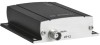
EN | 22 Installation and Operating Manual | VIP X1 Network You can connect the VIP X1 to a 10/100 Base-T network using a standard UTP category 5 cable with RJ45 connectors. - Connect the unit to the network using the ETH socket. Alarm inputs The VIP X1 has four alarm inputs on the orange terminal block (for pin assignment, see page 127). The alarm inputs are used to connect to external alarm devices such as door contacts or sensors. With the appropriate configuration, an alarm sensor can automatically connect the VIP X1 to a remote location, for example. A zero potential make contact or switch can be used as the actuator. Note If possible, use a bounce-free contact system as the actuator. - Connect the lines to the appropriate terminals on the orange terminal block (IN1 to IN4) and check that the connection is secure. Relay output The VIP X1 has a relay output for switching external units such as lamps or sirens. This relay output can be activated manually during a connection session with the VIP X1. The output can also be configured to automatically activate sirens or other alarm units in response to an alarm signal. The relay output is also located on the orange terminal block (for pin assignment, see page 128). Caution The maximum rating of the relay contact is 30 V and 2 A. - Connect the lines to the appropriate terminals on the orange terminal block (R) and check that the connection is secure. Installation Bosch Security Systems | 2006-12 | V2.5
-
 1
1 -
2
-
3
-
4
-
5
-
6
-
7
-
8
-
9
-
10
-
11
-
12
-
13
-
14
-
15
-
16
-
 17
17 -
 18
18 -
 19
19 -
 20
20 -
 21
21 -
 22
22 -
 23
23 -
 24
24 -
 25
25 -
 26
26 -
 27
27 -
28
-
29
-
30
-
31
-
32
-
33
-
34
-
35
-
36
-
37
-
38
-
39
-
40
-
41
-
42
-
43
-
44
-
45
-
46
-
47
-
48
-
49
-
50
-
51
-
52
-
53
-
54
-
55
-
56
-
57
-
58
-
59
-
60
-
61
-
62
-
63
-
64
-
65
-
66
-
67
-
68
-
69
-
70
-
71
-
72
-
73
-
74
-
75
-
76
-
77
-
78
-
79
-
80
-
81
-
82
-
83
-
84
-
85
-
86
-
87
-
88
-
89
-
90
-
91
-
92
-
93
-
94
-
95
-
96
-
97
-
98
-
99
-
100
-
101
-
102
-
103
-
104
-
105
-
106
-
107
-
108
-
109
-
110
-
111
-
112
-
113
-
114
-
115
-
116
-
117
-
118
-
119
-
120
-
121
-
122
-
123
-
124
-
125
-
126
-
127
-
128
-
129
-
130
-
131
-
132
-
133
-
134
-
135
-
136
-
137
-
138
-
139
-
140
-
141
-
142
-
143
-
144
 |
 |
