Brother International BAS-326G PS Instruction Manual - English - Page 19
Installing the pneumatic unit, INSTALLATION, <Adjusting the speed controller>
 |
View all Brother International BAS-326G PS manuals
Add to My Manuals
Save this manual to your list of manuals |
Page 19 highlights
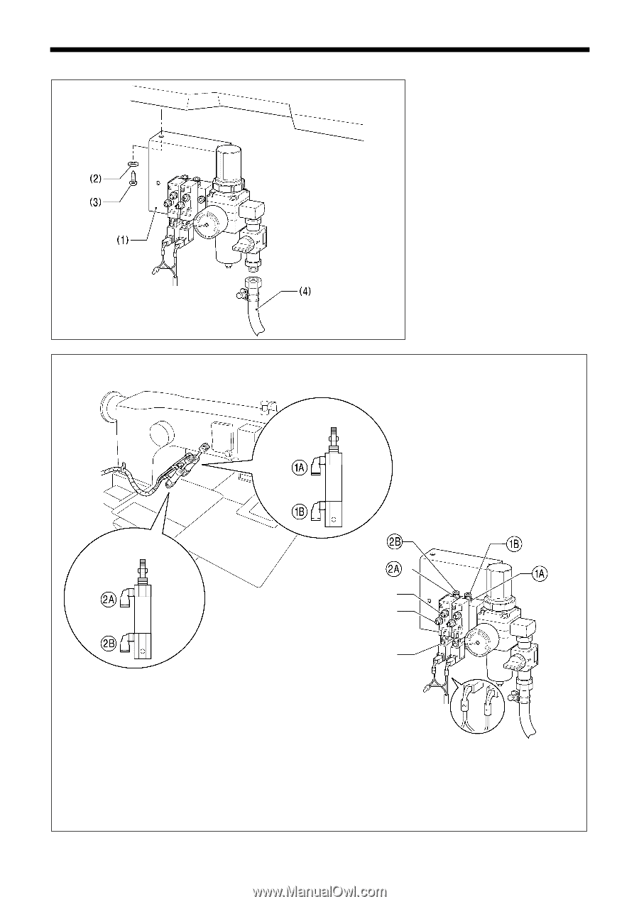
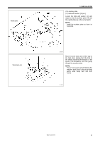
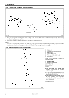
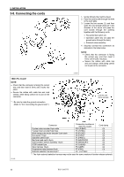
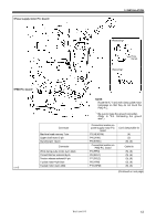
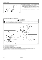
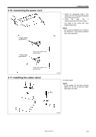
3-7. Installing the pneumatic unit 3. INSTALLATION Install underneath the work table. (1) Solenoid valve assembly (2) Washers [2 pcs.] (3) Wood screws [2 pcs.] (4) Rubber hose After installing the pneumatic unit, adjust the air pressure. (Refer to "10-16. Adjusting the air pressure".) NOTE: Make sure that the pneumatic unit does not touch the control box or the work table leg. Connect each air tube to the position with the corresponding number. 1904B Cylinder R Cylinder L Upper knob Lower knob Manual button You can use the valve knobs to adjust the lifting and lowering speeds. The valve knobs should be adjusted so that the left and right sides of the work clamp operate at the same speed. • When the upper knob is tightened, the lifting speed becomes slower. When it is loosened, the lifting speed becomes faster. • When the lower knob is tightened, the lowering speed becomes slower. When it is loosened, the lowering speed becomes faster. You can operate the work clamp while the power is turned off by pressing the manual button. 5220Q 1905B BAS-326G PS 10
-
 1
1 -
2
-
3
-
4
-
5
-
6
-
7
-
8
-
9
-
10
-
11
-
12
-
13
-
 14
14 -
 15
15 -
 16
16 -
 17
17 -
 18
18 -
 19
19 -
 20
20 -
 21
21 -
 22
22 -
 23
23 -
 24
24 -
25
-
26
-
27
-
28
-
29
-
30
-
31
-
32
-
33
-
34
-
35
-
36
-
37
-
38
-
39
-
40
-
41
-
42
-
43
-
44
-
45
-
46
-
47
-
48
-
49
-
50
-
51
-
52
-
53
-
54
-
55
-
56
-
57
-
58
-
59
-
60
-
61
-
62
-
63
-
64
-
65
-
66
-
67
-
68
-
69
-
70
-
71
-
72
-
73
-
74
-
75
-
76
-
77
-
78
-
79
-
80
-
81
-
82
-
83
-
84
 |
 |