Brother International BAS-326G PS Instruction Manual - English - Page 62
STANDARD ADJUSTMENTS, 10-1. Checking the machine head switch, 10-2. Arm thread guide R
 |
View all Brother International BAS-326G PS manuals
Add to My Manuals
Save this manual to your list of manuals |
Page 62 highlights
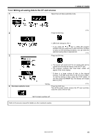
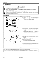
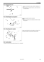
10. STANDARD ADJUSTMENTS 10. STANDARD ADJUSTMENTS CAUTION Maintenance and inspection of the sewing machine should only be carried out by a qualified technician. Ask your Brother dealer or a qualified electrician to carry out any maintenance and inspection of the electrical system. Hold the machine head with both hands when tilting it back or returning it to its original position. In addition, do not apply excessive force when tilting back the machine head. The sewing machine may become unbalanced and fall down, and serious injury or damage to the sewing machine may result. Turn off the power switch and disconnect the power cord before carrying out the following operations. If the foot switch is depressed by mistake, the sewing machine might start operating and injury could result. • Inspection, adjustment and maintenance • Replacing consumable parts such as the rotary hook If the power switch needs to be left on when carrying out some adjustment, be extremely careful to observe all safety precautions. If any safety devices have been removed, be absolutely sure to re-install them to their original positions and check that they operate correctly before using the machine. 10-1. Checking the machine head switch Check that the machine head switch is turned on as shown in the illustration. NOTE: If the machine head switch is not turned on, errors "E050", "E051" and "E055" will be generated. 10-2. Arm thread guide R More thread 1879B Less thread Index mark The standard position of arm thread guide R (1) is when the screw (2) is aligned with the index mark. Loosen the screw (2) and move arm thread guide R (1) to adjust. * When sewing heavy material, move arm thread guide R (1) to the left. (The thread take-up amount will become greater.) * When sewing light material, move arm thread guide R (1) to the right. (The thread take-up amount will become less.) 5030Q 53 BAS-326G PS
-
 1
1 -
2
-
3
-
4
-
5
-
6
-
7
-
8
-
9
-
10
-
11
-
12
-
13
-
14
-
15
-
16
-
17
-
18
-
19
-
20
-
21
-
22
-
23
-
24
-
25
-
26
-
27
-
28
-
29
-
30
-
31
-
32
-
33
-
34
-
35
-
36
-
37
-
38
-
39
-
40
-
41
-
42
-
43
-
44
-
45
-
46
-
47
-
48
-
49
-
50
-
51
-
52
-
53
-
54
-
55
-
56
-
 57
57 -
 58
58 -
 59
59 -
 60
60 -
 61
61 -
 62
62 -
 63
63 -
 64
64 -
 65
65 -
 66
66 -
 67
67 -
68
-
69
-
70
-
71
-
72
-
73
-
74
-
75
-
76
-
77
-
78
-
79
-
80
-
81
-
82
-
83
-
84
 |
 |