Brother International BAS-326G PS Instruction Manual - English - Page 67
In addition
 |
View all Brother International BAS-326G PS manuals
Add to My Manuals
Save this manual to your list of manuals |
Page 67 highlights
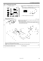
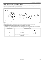
4950Q 10. STANDARD ADJUSTMENTS 1896B 1889B 7. Turn the pulley (1) by hand to move the needle bar to its lowest position. 8. Loosen the four bolts (10) and the nut (11) until the thread trimmer roller (3) is within the groove in the thread trimmer cam (4). After this, tighten the set screw (12) until the thread trimmer roller (3) is touching the inside of the groove in the thread trimmer cam (4) and then turn it back in the counterclockwise direction by approximately 1/4 of a turn. Then tighten the nut (11). 9. Slide solenoid setting plate U (15) in the direction of the arrow until it pushes against the cover (13) of thread trimmer solenoid B and the cushion (14), and then tighten the four bolts (10). 10. Loosen the nut (11) once more, and then turn the set screw (12) a further 1/4 of a turn in the counterclockwise direction. 11. Tighten the nut (11), and then check that the collar (3) is not touching the inside of the groove in the thread trimmer cam (4). In addition, push the driving lever (5) by hand toward the thread trimmer cam (4) until the collar (3) touches the groove of the thread trimmer cam (4), and then check that the driving lever (5) returns smoothly to its original position when it is released. 12. Check that there is a gap of about 8.5 - 9.5 mm between the tip of the movable knife (8) and the center of the hole in the needle hole plate (16) when there is still play between the parts. 1888B BAS-326G PS 58
-
 1
1 -
2
-
3
-
4
-
5
-
6
-
7
-
8
-
9
-
10
-
11
-
12
-
13
-
14
-
15
-
16
-
17
-
18
-
19
-
20
-
21
-
22
-
23
-
24
-
25
-
26
-
27
-
28
-
29
-
30
-
31
-
32
-
33
-
34
-
35
-
36
-
37
-
38
-
39
-
40
-
41
-
42
-
43
-
44
-
45
-
46
-
47
-
48
-
49
-
50
-
51
-
52
-
53
-
54
-
55
-
56
-
57
-
58
-
59
-
60
-
61
-
 62
62 -
 63
63 -
 64
64 -
 65
65 -
 66
66 -
 67
67 -
 68
68 -
 69
69 -
 70
70 -
 71
71 -
 72
72 -
73
-
74
-
75
-
76
-
77
-
78
-
79
-
80
-
81
-
82
-
83
-
84
 |
 |
