Brother International BAS-326G PS Instruction Manual - English - Page 72
STANDARD ADJUSTMENTS, <Stepping clamp connecting rod position adjustment>
 |
View all Brother International BAS-326G PS manuals
Add to My Manuals
Save this manual to your list of manuals |
Page 72 highlights
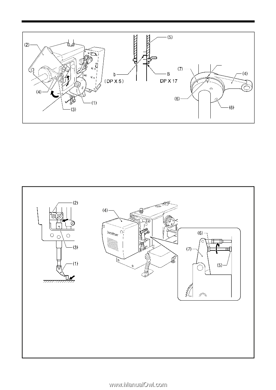
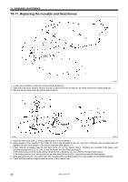
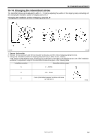
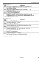
10. STANDARD ADJUSTMENTS 5014Q Index mark 5013Q 5015Q 1. Loosen the screw (1), and then open the cover (2). 2. Loosen the nut (3), and then adjust the position of the stepping clamp connecting rod (4). • When the stepping clamp connecting rod (4) is raised, the intermittent stroke will increase. • When the stepping clamp connecting rod (4) is lowered, the intermittent stroke will decrease. Next, adjust the needle bar and intermittent presser foot timing. 3. Turn the machine pulley to raise the needle bar from the lowest position until the lowest reference line on the needle bar (reference line B) is aligned with the lower edge of the needle bar bush (5). (If using a DP x 5 needle, align with the second reference line from the top (reference line b). 4. Open the top cover and loosen the two set screws (6). 5. Align the index marks on the stepping clamp cam (7) and the stepping clamp connecting rod (4), and then tighten the set screws (6). Check the following after changing the intermittent stroke. 5016Q 1895B Needle plate 1. With the intermittent presser foot (1) lowered, turn the pulley to move the intermittent presser foot (1) to its lowest position. 2. Check that the intermittent presser foot (1) does not touch the needle plate and that the presser bar clamp (2) does not touch the presser bar bush (3). Remove the motor cover (4). Loosen the nut (5), and turn the bolt (6) until it is pressing against the intermittent drive lever (7), and then adjust until the two points mentioned above are not touching. 63 BAS-326G PS
-
 1
1 -
2
-
3
-
4
-
5
-
6
-
7
-
8
-
9
-
10
-
11
-
12
-
13
-
14
-
15
-
16
-
17
-
18
-
19
-
20
-
21
-
22
-
23
-
24
-
25
-
26
-
27
-
28
-
29
-
30
-
31
-
32
-
33
-
34
-
35
-
36
-
37
-
38
-
39
-
40
-
41
-
42
-
43
-
44
-
45
-
46
-
47
-
48
-
49
-
50
-
51
-
52
-
53
-
54
-
55
-
56
-
57
-
58
-
59
-
60
-
61
-
62
-
63
-
64
-
65
-
66
-
 67
67 -
 68
68 -
 69
69 -
 70
70 -
 71
71 -
 72
72 -
 73
73 -
 74
74 -
 75
75 -
 76
76 -
 77
77 -
78
-
79
-
80
-
81
-
82
-
83
-
84
 |
 |