Brother International BAS-326G PS Instruction Manual - English - Page 71
Changing the intermittent stroke, STANDARD ADJUSTMENTS
 |
View all Brother International BAS-326G PS manuals
Add to My Manuals
Save this manual to your list of manuals |
Page 71 highlights
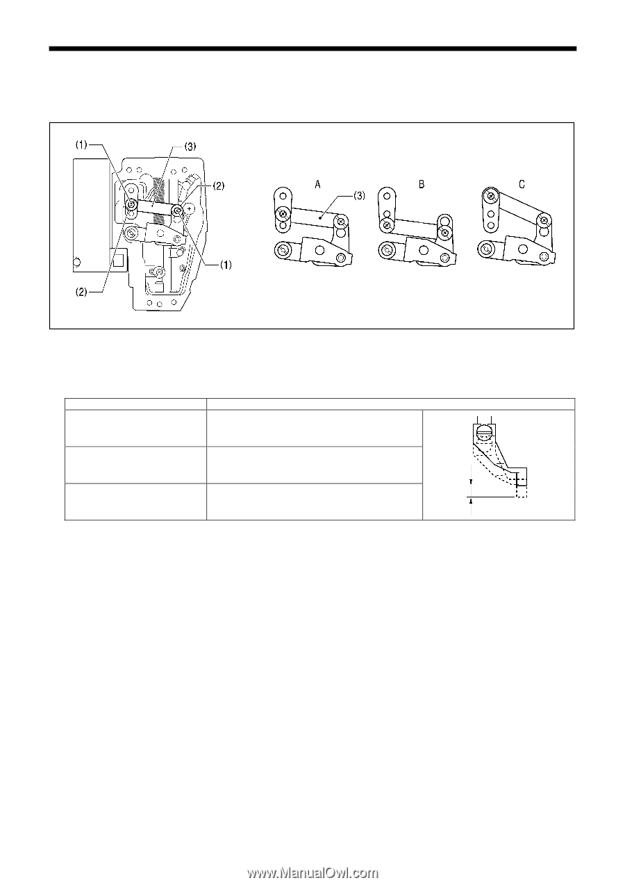
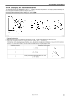
10. STANDARD ADJUSTMENTS 10-14. Changing the intermittent stroke The intermittent stroke can be adjusted to within 2 − 10 mm by adjusting the position of the stepping clamp connecting rod and changing the installation position of stepping clamp link A. 5010Q 5011Q 1. Remove the face plate. 2. Remove the two screws (1) and the two shoulder screws (2), and then remove stepping clamp link A (3). 3. Change the installation position for stepping clamp link A (3) to either A, B or C above. If the position of the stepping clamp connecting rod is adjusted as described in the following at any one of the installation positions, the adjustment range for the intermittent stroke will as given in the following table. Installation position Intermittent stroke range A 2 − 4.5mm B 4.5 − 10mm C 0 mm (Intermittent presser foot does not move up and down) 5012Q BAS-326G PS 62
-
 1
1 -
2
-
3
-
4
-
5
-
6
-
7
-
8
-
9
-
10
-
11
-
12
-
13
-
14
-
15
-
16
-
17
-
18
-
19
-
20
-
21
-
22
-
23
-
24
-
25
-
26
-
27
-
28
-
29
-
30
-
31
-
32
-
33
-
34
-
35
-
36
-
37
-
38
-
39
-
40
-
41
-
42
-
43
-
44
-
45
-
46
-
47
-
48
-
49
-
50
-
51
-
52
-
53
-
54
-
55
-
56
-
57
-
58
-
59
-
60
-
61
-
62
-
63
-
64
-
65
-
 66
66 -
 67
67 -
 68
68 -
 69
69 -
 70
70 -
 71
71 -
 72
72 -
 73
73 -
 74
74 -
 75
75 -
 76
76 -
77
-
78
-
79
-
80
-
81
-
82
-
83
-
84
 |
 |