Brother International BE-1204B Stand Alone Type Instruction Manual - English - Page 149
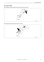
Move the needle bar case to the needle bar No.1 position., assembly, then fully tighten the bolt [4].
 |
View all Brother International BE-1204B manuals
Add to My Manuals
Save this manual to your list of manuals |
Page 149 highlights
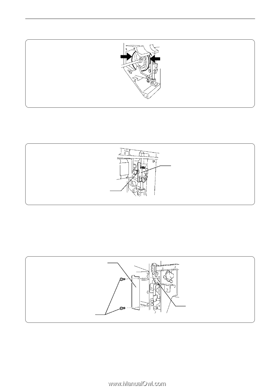
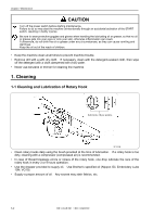
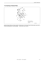
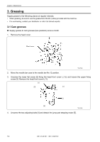
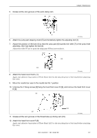
5. Grease all the cam grooves of the work clamp cam. Chapter 7 Maintenance W1297Q 6. Attach the jump part stepping motor [5] and tentatively tighten the adjusting bolt [4]. 7. Adjust the position of the bolt [4] so that the jump part [6] touches the roller [7] of the jump lever assembly, then fully tighten the bolt [4]. Adjust the roller [7] not to push the jump part [6] but just touches it. [6] [7] W1298Q 8. Attach the head cover front L [1]. Apply seal adhesive (equivalent of Three Bond 1215) to the attaching face of the head before attaching the cover. 9. Move the needle bar case to the needle bar No.1 position. 10. Unscrew the 2 fixing screws [8] fixing the head front cover R [9], and remove the head front cover R [9]. [9] [10] [8] 11. Grease all the cam grooves of the thread take-up driving cam [10]. W1299Q 12. Attach the head front cover R [9]. Apply seal adhesive (equivalent of Three Bond 1215) to the attaching face of the head before attaching the cover. BE-1204B-BC • BE-1206B-BC 7-7
-
 1
1 -
2
-
3
-
4
-
5
-
6
-
7
-
8
-
9
-
10
-
11
-
12
-
13
-
14
-
15
-
16
-
17
-
18
-
19
-
20
-
21
-
22
-
23
-
24
-
25
-
26
-
27
-
28
-
29
-
30
-
31
-
32
-
33
-
34
-
35
-
36
-
37
-
38
-
39
-
40
-
41
-
42
-
43
-
44
-
45
-
46
-
47
-
48
-
49
-
50
-
51
-
52
-
53
-
54
-
55
-
56
-
57
-
58
-
59
-
60
-
61
-
62
-
63
-
64
-
65
-
66
-
67
-
68
-
69
-
70
-
71
-
72
-
73
-
74
-
75
-
76
-
77
-
78
-
79
-
80
-
81
-
82
-
83
-
84
-
85
-
86
-
87
-
88
-
89
-
90
-
91
-
92
-
93
-
94
-
95
-
96
-
97
-
98
-
99
-
100
-
101
-
102
-
103
-
104
-
105
-
106
-
107
-
108
-
109
-
110
-
111
-
112
-
113
-
114
-
115
-
116
-
117
-
118
-
119
-
120
-
121
-
122
-
123
-
124
-
125
-
126
-
127
-
128
-
129
-
130
-
131
-
132
-
133
-
134
-
135
-
136
-
137
-
138
-
139
-
140
-
141
-
142
-
143
-
 144
144 -
 145
145 -
 146
146 -
 147
147 -
 148
148 -
 149
149 -
 150
150 -
 151
151 -
 152
152 -
 153
153 -
 154
154 -
155
-
156
-
157
-
158
-
159
-
160
-
161
-
162
-
163
-
164
-
165
-
166
-
167
-
168
-
169
-
170
-
171
-
172
-
173
-
174
-
175
-
176
-
177
-
178
-
179
-
180
-
181
-
182
-
183
-
184
-
185
-
186
 |
 |