Brother International BE-1204B Stand Alone Type Instruction Manual - English - Page 157
], then move the needle bar up and down until the needle tip touches the gauge [2] lightly.
 |
View all Brother International BE-1204B manuals
Add to My Manuals
Save this manual to your list of manuals |
Page 157 highlights
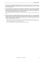
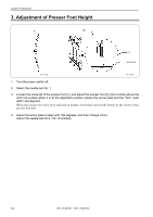
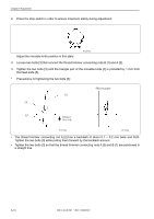
Chapter 8 Adjustment 1. Put the attached T-shaped hexagonal wrench (4 mm) into the hole [1] on the left side of the machine body, and adjust the arrow plate to align with 180 degrees (N.D mark) to move the needle bar to the lowest point. 2. Insert the bottom dead center gauge [2] into the rotary hook [3]. 3. Loosen the screw [5] of the needle bar clamp [4] and Socket head bolt for top dead center stopper [8], then move the needle bar up and down until the needle tip touches the gauge [2] lightly. • The needle point should touch the gauge at a place other than the cutting section. • The bottom dead center gauge should be set in or removed from the rotary hook with its cutting section facing upward. 4. Tighten the screw [5] of the needle bar clamp [4] securely. 5. Set the needle bar at the highest position (where the arrow plate and the "N.U."mark are aligned). Lightly press the top dead center stopper [6] toward the cushion rubber [7], and tighten Socket head bolt for top dead center stopper [8] while pressing down the needle bar clamp so that it faces the front. (Tightening torque: 0.78 N.m) • Make sure that the top dead center stopper [6] does not hit the needle bar guide rail [9] at this time. • When tightening the upper dead point stopper bolt [8], insert the longer side of the attached wrench into the bolt and tighten it by using the shorter side. Excessive tightening may make the needle bar movement sluggish. BE-1204B-BC • BE-1206B-BC 8-5
-
 1
1 -
2
-
3
-
4
-
5
-
6
-
7
-
8
-
9
-
10
-
11
-
12
-
13
-
14
-
15
-
16
-
17
-
18
-
19
-
20
-
21
-
22
-
23
-
24
-
25
-
26
-
27
-
28
-
29
-
30
-
31
-
32
-
33
-
34
-
35
-
36
-
37
-
38
-
39
-
40
-
41
-
42
-
43
-
44
-
45
-
46
-
47
-
48
-
49
-
50
-
51
-
52
-
53
-
54
-
55
-
56
-
57
-
58
-
59
-
60
-
61
-
62
-
63
-
64
-
65
-
66
-
67
-
68
-
69
-
70
-
71
-
72
-
73
-
74
-
75
-
76
-
77
-
78
-
79
-
80
-
81
-
82
-
83
-
84
-
85
-
86
-
87
-
88
-
89
-
90
-
91
-
92
-
93
-
94
-
95
-
96
-
97
-
98
-
99
-
100
-
101
-
102
-
103
-
104
-
105
-
106
-
107
-
108
-
109
-
110
-
111
-
112
-
113
-
114
-
115
-
116
-
117
-
118
-
119
-
120
-
121
-
122
-
123
-
124
-
125
-
126
-
127
-
128
-
129
-
130
-
131
-
132
-
133
-
134
-
135
-
136
-
137
-
138
-
139
-
140
-
141
-
142
-
143
-
144
-
145
-
146
-
147
-
148
-
149
-
150
-
151
-
 152
152 -
 153
153 -
 154
154 -
 155
155 -
 156
156 -
 157
157 -
 158
158 -
 159
159 -
 160
160 -
 161
161 -
 162
162 -
163
-
164
-
165
-
166
-
167
-
168
-
169
-
170
-
171
-
172
-
173
-
174
-
175
-
176
-
177
-
178
-
179
-
180
-
181
-
182
-
183
-
184
-
185
-
186
 |
 |