Brother International BE-1204B Stand Alone Type Instruction Manual - English - Page 158
Attachment and Adjustment of Rotary Hook
 |
View all Brother International BE-1204B manuals
Add to My Manuals
Save this manual to your list of manuals |
Page 158 highlights
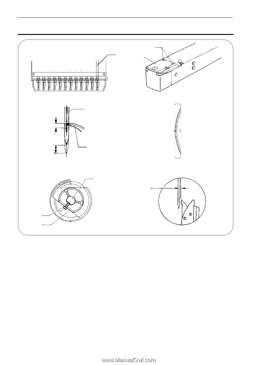
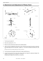
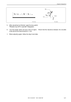
Chapter 8 Adjustment 2. Attachment and Adjustment of Rotary Hook [2] [1] [3] [6] 1.8 mm 1.7 mm W1309Q [4] W1310Q [5] W1311Q Lower shaft 0.1~0.3mm W1314Q [6] Cutting section W1312Q W1313Q 1. Turn the power switch off. 2. Select the needle bar No. 1 [1]. 3. Remove two flat screws [2] and dismount the needle plate [3]. 4. Adjust so that the needle [4] and the point of rotary hook [5] should meet at the position (where the arrow plate aligns with N.H mark (200 û)) higher by 1.7 mm than the needle bar lowest point (180 û ). Perform this after the height adjustment of the needle bar. 5. Turn the rotary hook manually until the point of rotary hook [5] turns up. 6. Loosen the screw [6] of the rotary hook cutting section and adjust the clearance between the needle and the rotary hook to be within 0.1 to 0.3 mm. Confirm that the height of the needle bar is 1.8 mm then. 8-6 BE-1204B-BC • BE-1206B-BC
-
 1
1 -
2
-
3
-
4
-
5
-
6
-
7
-
8
-
9
-
10
-
11
-
12
-
13
-
14
-
15
-
16
-
17
-
18
-
19
-
20
-
21
-
22
-
23
-
24
-
25
-
26
-
27
-
28
-
29
-
30
-
31
-
32
-
33
-
34
-
35
-
36
-
37
-
38
-
39
-
40
-
41
-
42
-
43
-
44
-
45
-
46
-
47
-
48
-
49
-
50
-
51
-
52
-
53
-
54
-
55
-
56
-
57
-
58
-
59
-
60
-
61
-
62
-
63
-
64
-
65
-
66
-
67
-
68
-
69
-
70
-
71
-
72
-
73
-
74
-
75
-
76
-
77
-
78
-
79
-
80
-
81
-
82
-
83
-
84
-
85
-
86
-
87
-
88
-
89
-
90
-
91
-
92
-
93
-
94
-
95
-
96
-
97
-
98
-
99
-
100
-
101
-
102
-
103
-
104
-
105
-
106
-
107
-
108
-
109
-
110
-
111
-
112
-
113
-
114
-
115
-
116
-
117
-
118
-
119
-
120
-
121
-
122
-
123
-
124
-
125
-
126
-
127
-
128
-
129
-
130
-
131
-
132
-
133
-
134
-
135
-
136
-
137
-
138
-
139
-
140
-
141
-
142
-
143
-
144
-
145
-
146
-
147
-
148
-
149
-
150
-
151
-
152
-
 153
153 -
 154
154 -
 155
155 -
 156
156 -
 157
157 -
 158
158 -
 159
159 -
 160
160 -
 161
161 -
 162
162 -
 163
163 -
164
-
165
-
166
-
167
-
168
-
169
-
170
-
171
-
172
-
173
-
174
-
175
-
176
-
177
-
178
-
179
-
180
-
181
-
182
-
183
-
184
-
185
-
186
 |
 |