Brother International BE-1204B Stand Alone Type Instruction Manual - English - Page 177
tension base PCB if it does not blink.
 |
View all Brother International BE-1204B manuals
Add to My Manuals
Save this manual to your list of manuals |
Page 177 highlights
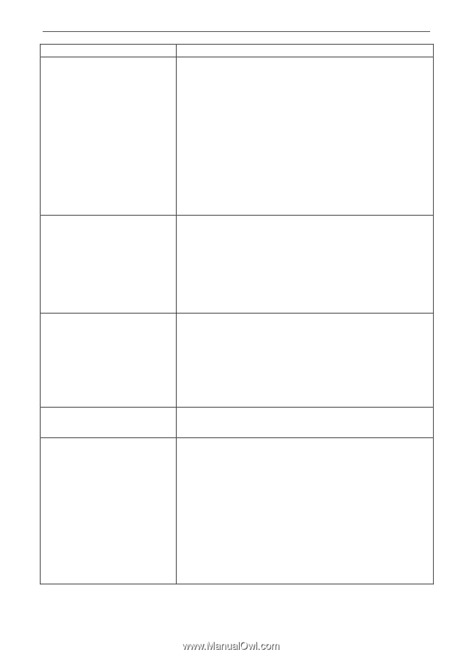
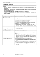
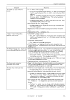
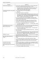
Chapter 10 Troubleshooting Symptom The needle bar case lock error occurs. X-axis or Y-axis home position detection error occurs. The thread breakage error frequently occurs although thread is not broken. The X-axis motor connector connection error occurs. The main shaft motor lock error occurs. Measures • Is the INDEX motor rotating? → If not, refer to the block diagram showing the cable connections and check to see if connection from the INDEX motor to the main PCB is proper. Check the resistance values of pins 1 and 3 and pins 4 and 6 at the connector section of the INDEX motor. The normal resistance value is approximately 6.6Ω. → If it is not normal, replace the INDEX motor with a new one. Also replace the drive PCB with a new one. • Manually turn the color change pulley. → If it is abnormally heavy, adjust the color change mechanism and the needle cap case. • Replace the needle bar position sensor (potentiometer) with a new one. • Replace the I/O PCB 0 with a new one. • Was the XY carriage moving? → If so, refer to the block diagram showing the cable connections and check to see if connection from the X and Y area sensor to the drive PCB is proper. • Was the XY motor rotating? → If so, check the XY carriage mechanism. • If the XY motor is not rotating, refer to the cable connection block diagram and check to see if connection from the XY motor to the drive PCB is proper. • Enter the CASE test mode and turn the thread breakage sensor pulley corresponding to each needle bar of the head with which this error occurs while switching the needle bar from number 1 in ascending order and check to see that the red LED on the head blinks. → If there is no problem, lower the thread breakage sensitivity value of the machine controller. (The standard value is 0.) • Check connection from the thread breakage sensor PCB to the thread tension base PCB if it does not blink. • Replace the thread breakage sensor PCB with a new one. • Refer to the block diagram showing the cable connections and check the connection from the two X motors (one X motors in four head models) on the left and right to the main PCB. • Enter the encoder signal mode and manually turn the main shaft pulley. → If it is abnormally heavy, the main shaft mechanism is faulty. • Does the main shaft motor rotate at all when the error occurs? → If it does not rotate at all, check fuse F1 and F2 on the power supply PCB in the control box. Refer to the block diagram showing the cable connections and check to see if connection from the main shaft motor to the drive PCB is proper. • Manually turn the main shaft pulley in the encoder signal test mode and check to see if the stop position signal and encoder signal are proper. → If either of the signals does not change, refer to the block diagram showing the cable connections and check to see if connection from the encoder and stop position sensor to the power supply PCB is proper. BE-1204B-BC • BE-1206B-BC 10-5
-
 1
1 -
2
-
3
-
4
-
5
-
6
-
7
-
8
-
9
-
10
-
11
-
12
-
13
-
14
-
15
-
16
-
17
-
18
-
19
-
20
-
21
-
22
-
23
-
24
-
25
-
26
-
27
-
28
-
29
-
30
-
31
-
32
-
33
-
34
-
35
-
36
-
37
-
38
-
39
-
40
-
41
-
42
-
43
-
44
-
45
-
46
-
47
-
48
-
49
-
50
-
51
-
52
-
53
-
54
-
55
-
56
-
57
-
58
-
59
-
60
-
61
-
62
-
63
-
64
-
65
-
66
-
67
-
68
-
69
-
70
-
71
-
72
-
73
-
74
-
75
-
76
-
77
-
78
-
79
-
80
-
81
-
82
-
83
-
84
-
85
-
86
-
87
-
88
-
89
-
90
-
91
-
92
-
93
-
94
-
95
-
96
-
97
-
98
-
99
-
100
-
101
-
102
-
103
-
104
-
105
-
106
-
107
-
108
-
109
-
110
-
111
-
112
-
113
-
114
-
115
-
116
-
117
-
118
-
119
-
120
-
121
-
122
-
123
-
124
-
125
-
126
-
127
-
128
-
129
-
130
-
131
-
132
-
133
-
134
-
135
-
136
-
137
-
138
-
139
-
140
-
141
-
142
-
143
-
144
-
145
-
146
-
147
-
148
-
149
-
150
-
151
-
152
-
153
-
154
-
155
-
156
-
157
-
158
-
159
-
160
-
161
-
162
-
163
-
164
-
165
-
166
-
167
-
168
-
169
-
170
-
171
-
 172
172 -
 173
173 -
 174
174 -
 175
175 -
 176
176 -
 177
177 -
 178
178 -
 179
179 -
 180
180 -
 181
181 -
 182
182 -
183
-
184
-
185
-
186
 |
 |