Brother International BE-1204B Stand Alone Type Instruction Manual - English - Page 41
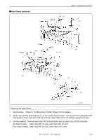
Holder base optional, Remove 4 bolts [9] from the front of X-feed sash [8].
 |
View all Brother International BE-1204B manuals
Add to My Manuals
Save this manual to your list of manuals |
Page 41 highlights
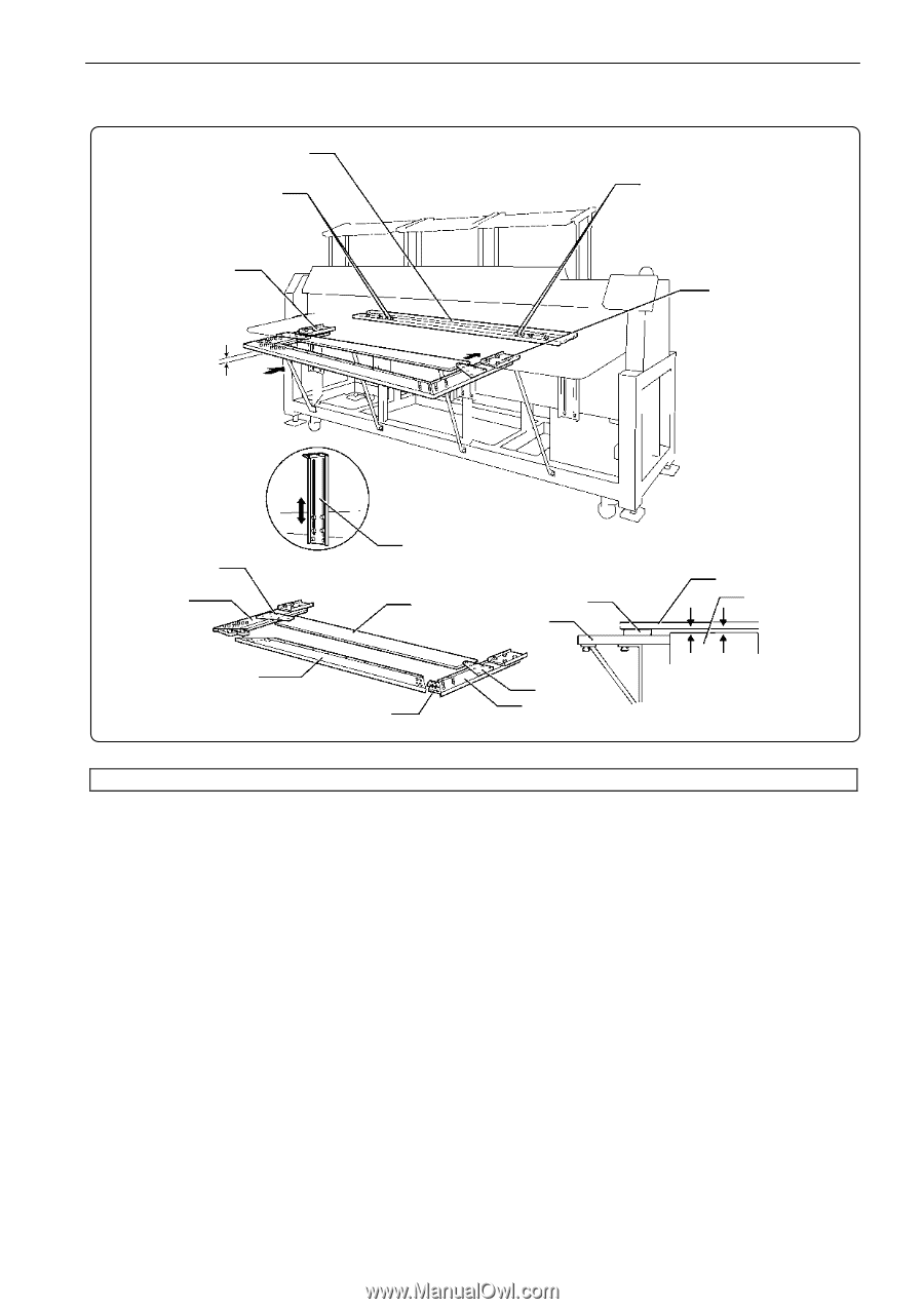
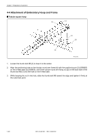
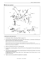
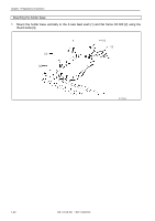
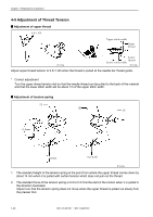
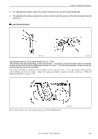
! Holder base (optional) [8] [9] [10] Chapter 1 Preparations of operation [9] [11] [5] [1] [2] [12] [7] [4] Felt Table [6] [3] [1] [3] Y-axis cover 1mm 1mm W1244Q Attaching the holder base frame 1. Set the table. (Refer to "Mounting of Table" on page 1-9.) 2. Insert the frame connecting plate F [4] into the holder base frame L [1], flat frame C6-360 [2] and holder base frame R [3], using bolts and washers. [When using the machine only with the holder base frame(small)] Attach the flat frame S connecting plates L [5] and R [6] to the flat frame S6-360 set [7]. Attach the flat frame S connecting plates L [5] and R [6] to the holder base frames L [1] and R [3], using bolts of 4×12 and washers of middle 4. 3. Remove 4 bolts [9] from the front of X-feed sash [8]. 4. Put the frame connecting plates L [10] and R [11] on the X-feed sash [8]. Fix them with bolts and washers. 5. Check that the clearance between the mounted flat frame C6-360 [2] and the table is even when viewed from the machine front. If adjustments are needed, loosen bolts of the F table support Front [12] and move it in the direction of the arrow. 6. Tighten each bolt securely after the adjustment is completed. BE-1204B-BC • BE-1206B-BC 1-21
-
 1
1 -
2
-
3
-
4
-
5
-
6
-
7
-
8
-
9
-
10
-
11
-
12
-
13
-
14
-
15
-
16
-
17
-
18
-
19
-
20
-
21
-
22
-
23
-
24
-
25
-
26
-
27
-
28
-
29
-
30
-
31
-
32
-
33
-
34
-
35
-
 36
36 -
 37
37 -
 38
38 -
 39
39 -
 40
40 -
 41
41 -
 42
42 -
 43
43 -
 44
44 -
 45
45 -
 46
46 -
47
-
48
-
49
-
50
-
51
-
52
-
53
-
54
-
55
-
56
-
57
-
58
-
59
-
60
-
61
-
62
-
63
-
64
-
65
-
66
-
67
-
68
-
69
-
70
-
71
-
72
-
73
-
74
-
75
-
76
-
77
-
78
-
79
-
80
-
81
-
82
-
83
-
84
-
85
-
86
-
87
-
88
-
89
-
90
-
91
-
92
-
93
-
94
-
95
-
96
-
97
-
98
-
99
-
100
-
101
-
102
-
103
-
104
-
105
-
106
-
107
-
108
-
109
-
110
-
111
-
112
-
113
-
114
-
115
-
116
-
117
-
118
-
119
-
120
-
121
-
122
-
123
-
124
-
125
-
126
-
127
-
128
-
129
-
130
-
131
-
132
-
133
-
134
-
135
-
136
-
137
-
138
-
139
-
140
-
141
-
142
-
143
-
144
-
145
-
146
-
147
-
148
-
149
-
150
-
151
-
152
-
153
-
154
-
155
-
156
-
157
-
158
-
159
-
160
-
161
-
162
-
163
-
164
-
165
-
166
-
167
-
168
-
169
-
170
-
171
-
172
-
173
-
174
-
175
-
176
-
177
-
178
-
179
-
180
-
181
-
182
-
183
-
184
-
185
-
186
 |
 |