Brother International LK3-B430 Service Manual
Brother International LK3-B430 Manual
 |
View all Brother International LK3-B430 manuals
Add to My Manuals
Save this manual to your list of manuals |
Brother International LK3-B430 manual content summary:
- Brother International LK3-B430 | Service Manual - Page 1
SERVICE MANUAL FOR BROTHER MODEL LK3-B430 .k.A" c.o.% -ow G• es a • BROTHER INDUSTRIES, LTD. NAGOYA, JAPAN - Brother International LK3-B430 | Service Manual - Page 2
tension release 33 • Thread wiper 34 STITCH."67A173.111G PROCEDURE` 35 • From ordinary stitches to knitted stitches 35 Q From ordinary stitches to denim stitches 36 • List of, replacement parts 17 THOUS CHA 39 - Brother International LK3-B430 | Service Manual - Page 3
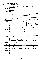
The table below shows the sub-classes of the LK3-6430 type high speed bar tacking machine. CBROTHER INDUSTRIES, LTD:\ LK3-6430 MADE INpAPAN J [ Sub-class Main uses Decorative stitching Number of stitches -1 -2 Ordinary clothes 1 i i i . , i I, i i i. O1 ' ! t t't t t i 'I i i 1 -3 Denim ' - Brother International LK3-B430 | Service Manual - Page 4
082105.0-90 (50) STANDARD • • - • _ • Sub-class Use Upper thread tension (g) Lower thread tension (g) Thread take-up spring Lower thread tension Thread take-up spring height 4lj kir+ . Start the machine, and measure as shown above. Thread take-up spring tension Measure as shown above. - Brother International LK3-B430 | Service Manual - Page 5
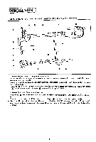
needle bar bushing U 0. needle bar bushing D 0 and needle bar guide slide block m to smoothly run up and down. (2) Lower Shaft and Shuttle Mechanism moves 4. When pulley O turns in the arrow direction. crank rode up and down via the crank part ® of the upper e. shaft. 5. The louer end of crank - Brother International LK3-B430 | Service Manual - Page 6
© low speed, roller of clutch cam0,and then moves onto gets into a recess of clutch cam ID. the low speed part ®. As the machine sews 4 stitches at e. (Stop When Lever) stop lver (1) is pushed in the arrow direction, roller 0 is released from roller holder 0 and gets into a recess - Brother International LK3-B430 | Service Manual - Page 7
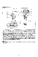
lower end of clutch actuating lever Q is pushed up so that roller 0 disengage: from the cam part QQ of power cam 0. Thus power cam 0 contacts power pulley 0 to be driven one half thread wiper arm shaft as support fulcrum, and actuates as fulcrum. thread wiper ®, which is connected to thread - Brother International LK3-B430 | Service Manual - Page 8
to tack width feed lever 0. similarly rocks. 3. Tack width lever m is connected to tack width regulator lever 0 with nut m so that it moves feed guides back and forth about tack width lever shafts as fulcrum. (2) Tack Length/ Mechanism 4. Roller 0 fits in the groove on the underside of feed cam 0 to - Brother International LK3-B430 | Service Manual - Page 9
MECHANISM 0• (I) 0 00 0 • i r O- (?) ID 0 1. When power cam 0 rotates one half of a turn in the arrow direction. roller 0 in contact with the cam part® of power cam 0 Oushed down so that the motionisconveyed via thread trimminglink to camlever 0 through driving shaft 0 as fulcrum. 2. Cam lever - Brother International LK3-B430 | Service Manual - Page 10
tension release lever shaft 0 as fulcrum. 2. When the machine is started, tension release pin 0 is at the cam part O: and when the stop cam reaches 90° ® ®. cam part O to release tension discs II) and simultaneously conveys the motion to thread take-up lever via guide stud which is fixed to guide - Brother International LK3-B430 | Service Manual - Page 11
machine head. and remove the V-belt. 9. Return the machine head. 10. Remove the chain. 2 PRESSER ARM I. Needle bar thread guide 0 0. Remove screw 0. needle 0. and then needle bar thread guide et, r„ O - C O- I 3 SHUTTLE I. Bobbin case 0 Remove bobbin case 0 by holding the latch. 2. Shuttle race - Brother International LK3-B430 | Service Manual - Page 12
Remove two screws Q and 0, and then thread take-up lever O. 4. Guide stud 0 Remove it by turning it with a screwdriver. ®, 5. Tension release relase bar plate 0. Ei POWER WORK CLAMP LIFTER I. Power pulley With the machine at the stop position, remove screw 0 and washer 0, and then power pulley - Brother International LK3-B430 | Service Manual - Page 13
m together with washer It can easily be removed if the pulley turning crank rod is at left as viewed from the rear of the machine. 0. 9. Brake assembly (D Loosen screw and remove brake assembly together with the shaft. !O. Ball presser plate Remove two bolts 0 and washers 0, and then ball - Brother International LK3-B430 | Service Manual - Page 14
the pulley, operate the emergency sotp lever until the knife cam lever claw dropps into the recess of the knife cam. 2. Raise the machine head. 3. Thread trimming arm A 0 Remove E-shaped stop ring 0, loosen screw 0, and remove thread trimming arm A 0. 4. Thread trimming arm B 0 Pull it upward of the - Brother International LK3-B430 | Service Manual - Page 15
the key. and tighten nut (left-handed). 2. Ball holder 0 Tighten ball holder 0 with four screws 0. (re 0 0 0 00 FSt r 0 0 a 2 THREAD TRIMMER I. Return the machine head onto the oil pan. 2. Knife cam lever 0 I) Pass the tip of connecting rod 0 through the bed. and tighten knife cam lever shaft - Brother International LK3-B430 | Service Manual - Page 16
5. Raise the machine head. 6. Thread trimming arm B Insert it from above the bed. 7. Thread trimming arm A Fit the pin into the tip of connecting rod 0. slide thread trimming - Brother International LK3-B430 | Service Manual - Page 17
rod is shifted to the left as viewed from the rear of the machine by turning the pulley. 6. Clutch actuating lever 0 e Insert it into the (2) Turn the pulley until clutch cam lever roller rides on the low speed part of clutch cam 0. (3) Adjust the gap between stopper and stop cam 01 to - Brother International LK3-B430 | Service Manual - Page 18
IT FEED 1. Raise the machine head. 2. Feed cam 0 With the stopper in contact with the stop cam (stop position), fit the cam lever roller into the cam groove, and install - Brother International LK3-B430 | Service Manual - Page 19
it to the tip of the tension release bar. and temporarily fasten it with two each screws 0 and washers 0. 2. Guide stud 0 Install it on the thread take-up guide bearing, using a screwdriver. 3. Thread take-up lever 0 Install it with two screws and 0. 4. Sub-tension 0 Temporarily fasten it to the arm - Brother International LK3-B430 | Service Manual - Page 20
bushing * If a DP X 17 needle is used. adjust it so the second lowest reference line C) . (2) After this adjustment. fit needle bar thread guide ID onto the needle bar. insert needle 0 into fasten it with screw S. - - (3) Raise the machine head. fit the driver onto the lower shaft, and - Brother International LK3-B430 | Service Manual - Page 21
7. Clearance between needle and shuttle hook Turn the pulley so that the point of the shuttle 0hook meets the center of the needle. Loosen screw and turn eccentric shaft so that the clearance between the point of the shuttle hook and the needle is 0.01 to 0.08 mm. 8. Clearance between needle and - Brother International LK3-B430 | Service Manual - Page 22
-tension Loosen screw and move the sub-tension in or out so that the tension disc presser will make a clearance of 0.5 to 1.0 mm at the machine stop position. 2. Main tension Loosen two screws O. and move tension release bar plate Q to the right or left so that the main tension discs will - Brother International LK3-B430 | Service Manual - Page 23
pie needle bar is flush with the lower end of the needle bar bushing OIf using a DP x 17 needle. adjust the needle bar so that the reference line second of the shuttle hook is in line with the center of the needle. * If using a DP x 17 needle. adjust the needle bar so that the lowest reference line - Brother International LK3-B430 | Service Manual - Page 24
4. Needle and shuttle hook clearance adjustment O. 01-0. 08mm - 0 -Turn the pulley to bring the top of the shuttle hook into line with the center of the needle. Then loosen screw() and turn the eccentric shaft Q so that the clearance between the needle and the top of the shuttle hook is 0.01 to 0. - Brother International LK3-B430 | Service Manual - Page 25
1. Tack width adjustment Turn the pulley by hand until the needle shown the Reference Needle Position on the preceding page (which varies with the specifications) falls into the needle hole. Loosen bolt O. and move the presser arm forward or back so that the needle falls in the center of the work - Brother International LK3-B430 | Service Manual - Page 26
adjustment 0- -0 / 0- -0 With the machine at the stop position (roller 0 riding on the projected part on the periphery of the feed cam). loosen much as to be free of vertical shaft play with the machine at the stop position. * After this adjustment. turn the machine by one cycle and make sure - Brother International LK3-B430 | Service Manual - Page 27
1. Stopper adjustment With the machine at the stop position. loosen nut and adjust nut 0 so that the bottom of stopper meets the end of clutch lever 0. 0-- 0 - Meet 0 O O 2. Clutch lever position adjustment 6±0.5ccra • t. 00- With clutch cam lever roller 0 on the low speed part 0 of clutch cam - Brother International LK3-B430 | Service Manual - Page 28
speed pulley m this adjustment, run the machine at high speed, turned by and make sure that the high speed pulley will not slip. * If. after years of use, the pulley slips even after the above-mentioned adjustment, refer to the pulley disassembly instructions on Page 12, remove one washer, and - Brother International LK3-B430 | Service Manual - Page 29
bolts 9 and move start safe lever 6) up or down so that the clearance between it and periphery of the power cam is 3 mm at the machine stop position. e 7. Start stopper position adjustment Loosen two bolts and move stoppers up or do%%n so that. %%hen the treadle is depressed two steps. the - Brother International LK3-B430 | Service Manual - Page 30
lever spring to the second position of the clutch lever spring hook. 10. Brake spring pressure adjustment If a very heavy material is sewn with the machine of the standard specifications, the stop cam might not turn all the way to the stop position upon sewing the last stitch due to increased - Brother International LK3-B430 | Service Manual - Page 31
slot 0 of the power cam is in line with the center of roller 0 at the machine stop position (with the work clamp up). If not. insert a screwdriver into the slot, is 0.5 mm. • 0 • Standard Work Clamp Height Use Ordinary, Knitted clothes Denim Work Clamp Height ' \lc .10 mm 15 mm t{ -31 - 0 0 - Brother International LK3-B430 | Service Manual - Page 32
its corner meets the mark 0 (outside) of the needle plate. -r (2) When the power pulley is turned little by little in the rotating direction at the machine stop position (with the work clamp down), knife cam lever claw 0 drops one step further. In this condition, loosen screw 0, and turn stud 0 so - Brother International LK3-B430 | Service Manual - Page 33
appropriate to the work to be sewn. (1) With the machine in operation. loosen screw O. and move guide shaft 0 to the right or left. The smaller the be within the mark range. 2. Main tension disc clearance adjustment With the machine at the stop position. loosen two screws 0 and move tension release - Brother International LK3-B430 | Service Manual - Page 34
E THREAD WIPER 1. Thread wiper height adjustment Loosen screw 0. and move thread wiper arm supporter 0 up or down so that the clearance between the wiper and the tip of the needle will be 2 mm when the wiper passes under the - Brother International LK3-B430 | Service Manual - Page 35
STITCHES TO KNITTED STITCHES • Necessary replacement parts Feed cam 0 Change gear C Change gear W Work clamps L. R Needle Feed guide 0 Needle hole plate 0 0 Ni 0 ..) -CD (Procedure) When changing the number of stitches. be sure to do so at the machine stop position. I. Install change gear - Brother International LK3-B430 | Service Manual - Page 36
work clamps L. R in place. and fasten work clamp guide brackets A 0) and B 0) with six e. screws G. the machine stop position. I. Refer to Steps I to 10 on the preceding page, and install the respective parts. the List of Replacement Parts on Page 37, and have the necessary parts ready on hand for stitch - Brother International LK3-B430 | Service Manual - Page 37
M LIST OF REPLACEMENT PARTS Nam0vab; Feed cam ra y 4--: S *)' , T1 Feed cam S (42 stitches) 152727-0-01 Feed cam S (28 stitches) 153054-0-01 Feed cam K (28 stitches) 153343-0-01 Feed cam K ( - Brother International LK3-B430 | Service Manual - Page 38
:64P> 7 11'.'"1",./.2.7 1 • Needle hole plate 7C 1(42711:: 42r,.:1 Needle hole plate B (inner diameter 2.2) 152909-0-01 t Needle Needle DP x 5 (#16) 107415-0-16 9.Shuttle hook • CIII)II:1 kl Shuttle hook A 152685-0-01 Shuttle race ring Shuttle race ring A 152682-0-01 Needle hole plate C ( - Brother International LK3-B430 | Service Manual - Page 39
roller holder lever position. 26 Ball presser plate is in wrong position in longitudinal directions in loss speed operation. Ball presser plate it Machine stops in low speed F,h i operation. Ball presser plate is in wrong position in sidewise direciuons in low speed operation. Clutch lever does - Brother International LK3-B430 | Service Manual - Page 40
High-speed pulley torque Adjust high-speed belt to yield about 10 mm Adjust ball presser plate 1 position, or remose pulley! 27 washer. d Machine position. does not run to slop rI - Clutch cam tinting -I Brake shoe contact timing Work clamp does not rise. .._iWork clamp lifter roller - Brother International LK3-B430 | Service Manual - Page 41
. Lower thread tension bracket position Adjust lower thread tension bracket position. Lower thread is not wound' enough. Bobbin presser position is wrong. Thread volume Adjust bobbin presser position. _I Main tension release timing is wrong. Clutch cam timing Adjust clutch cam timing. 28 - Brother International LK3-B430 | Service Manual - Page 42
thread tens:17 2 .1Adjust kisser thread tension. Needle hole plate or bobbin case edge has flaws. Thread retainer position is wrung. d Thread retainer position Flaws Needle and shuttle hook clearance Polish or replace delectise parts. Adjust minable knife I 32 position. Polish thread path. or - Brother International LK3-B430 | Service Manual - Page 43
• Trouble • C• ause Check' • . 11\091 , A rnie is blunt. r Thread trimming leser Iotal stitch skipping. Final stitch skipping. Adjust shuttle thread guide! /1 position. Ii I I Adjust needle bar stroke. 23 42 Refer to instructions for stitch skipping, and take steps to present it. - Brother International LK3-B430 | Service Manual - Page 44
MEMO -44- - Brother International LK3-B430 | Service Manual - Page 45
1 BROTHER INDUSTRIES, LTD. HEAD OFFICE: No. 35, 9-CHOME HORITA-DORI, MIZUHC-I NAGOYA, JAPAN . TELEX: BROTHER J59743.59908.59970 I 9110060 Printed in Japan
-
 1
1 -
 2
2 -
 3
3 -
 4
4 -
 5
5 -
 6
6 -
 7
7 -
8
-
9
-
10
-
11
-
12
-
13
-
14
-
15
-
16
-
17
-
18
-
19
-
20
-
21
-
22
-
23
-
24
-
25
-
26
-
27
-
28
-
29
-
30
-
31
-
32
-
33
-
34
-
35
-
36
-
37
-
38
-
39
-
40
-
41
-
42
-
43
-
44
-
45
 |
 |
SERVICE
MANUAL
FOR
BROTHER
MODEL
LK3-B430
.k.A"
c.o.%
-ow
G•
es
a
•
BROTHER
INDUSTRIES,
LTD.
NAGOYA,
JAPAN