Brother International LK3-B430 Service Manual - Page 13
Clutch, Brake
 |
View all Brother International LK3-B430 manuals
Add to My Manuals
Save this manual to your list of manuals |
Page 13 highlights
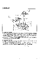
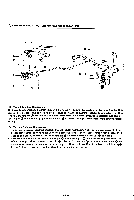
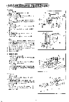
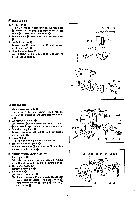
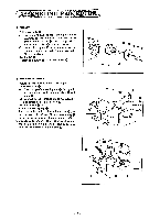
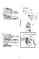
7 FEED 1. Raise the machine head. 2. Loosen screw Q. and pull out with 0 from tack length feed lever 0. 3. Tack length feed lever 0 Loosen bolt 0. remove tack length feed lever shaft 0 together with washer 0. and remove tack length feed lever 0 by moving it in the arrow direction. exercising care not to drop slide block 0. 4. Pull out pinch sleeve 0. 5. Feed cam 0 Remove bolt (t) and washer Q. 8 CLUTCH AND BRAKE I. Lower the machine head to the level position. 2. Emergency stop lever 0 Loosen screw 0 and remove emergency stop lever O. 3. Roller holder cover 0 Remove two screws 0. and then roller holder cover 0. Temporarily install emergency stop lever 0 after removing roller holder cover 0. 4. Clutch spring Disengage only the end of clutch spring 0 which is hooked to the spring hook. 5. Brake spring Disengage brake spring 0 from the spring hook. 6. Clutch cam lever 0 Loosen bolt 0. and remove clutch cam lever 0. Q, 7. Clutch actuating lever 0 Remove nut (r) and screw and then clutch actuating lever 0. 8. Tension release lever 0. Loosen screw •. and pull out tension release lever shaft m together with washer It can easily be removed if the pulley turning crank rod is at left as viewed from the rear of the machine. 0. 9. Brake assembly (D Loosen screw and remove brake assembly together with the shaft. !O. Ball presser plate Remove two bolts 0 and washers 0, and then ball presser plate m. Also remove steel ball 0, exercising care not to drop it. I I. Clutch lever assembly ( I) Remove nut (1) and eccentric screw 0. (2) Remove bolt ED, washer 12), and washer 0. 0. (3) After removing clutch lever assembly tip, remove washer 0- -0 -0 0 m - -0 0 0 O- fax 4 o- ONO 0 0 0 co 0
-
 1
1 -
2
-
3
-
4
-
5
-
6
-
7
-
 8
8 -
 9
9 -
 10
10 -
 11
11 -
 12
12 -
 13
13 -
 14
14 -
 15
15 -
 16
16 -
 17
17 -
 18
18 -
19
-
20
-
21
-
22
-
23
-
24
-
25
-
26
-
27
-
28
-
29
-
30
-
31
-
32
-
33
-
34
-
35
-
36
-
37
-
38
-
39
-
40
-
41
-
42
-
43
-
44
-
45
 |
 |
