Brother International LK3-B430 Service Manual - Page 15
Sem:mang, Procip
 |
View all Brother International LK3-B430 manuals
Add to My Manuals
Save this manual to your list of manuals |
Page 15 highlights
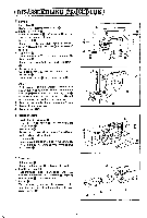
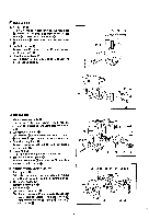
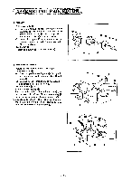
SEM:MANG 1PROCIP) I1 PULLEY I. Pulley assembly 0 ( I ) Fit spring 0 over the upper shaft. push pulley assembly 0 onto the upper shaft toward the arm. fit three washers 0 onto the upper shaft. and then insert key 0 into the keyway. (2) Install clutch plate 0 in such a way that the keyway is in line with the key. and tighten nut (left-handed). 2. Ball holder 0 Tighten ball holder 0 with four screws 0. (re 0 0 0 00 FSt r 0 0 a 2 THREAD TRIMMER I. Return the machine head onto the oil pan. 2. Knife cam lever 0 I) Pass the tip of connecting rod 0 through the bed. and tighten knife cam lever shaft 0 with screw 0. (2) Connect thread trimming link 0 with stud 0. and temporarily tighten screw 0. (3) Put oil cap 0 on. 3. Knife cam lever spring 0 Turn the pulley until knife cam lever claw m gets into the recess of knife came, and hook spring 0 to the pin at the bottom of knife cam lever 0. 4. Operate knife cam lever 0 in the arrow direction. and turn the pulley until the knife cam lever roller rides on the periphery of knife cam O. • 0 0 -' O - -0 0 0 • -13-
-
 1
1 -
2
-
3
-
4
-
5
-
6
-
7
-
8
-
9
-
 10
10 -
 11
11 -
 12
12 -
 13
13 -
 14
14 -
 15
15 -
 16
16 -
 17
17 -
 18
18 -
 19
19 -
 20
20 -
21
-
22
-
23
-
24
-
25
-
26
-
27
-
28
-
29
-
30
-
31
-
32
-
33
-
34
-
35
-
36
-
37
-
38
-
39
-
40
-
41
-
42
-
43
-
44
-
45
 |
 |
