Brother International LK3-B430 Service Manual - Page 9
Brother International LK3-B430 Manual
 |
View all Brother International LK3-B430 manuals
Add to My Manuals
Save this manual to your list of manuals |
Page 9 highlights
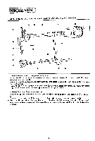
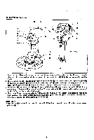
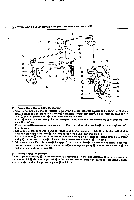
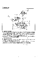
THREAD TRIMMER MECHANISM 0• (I) 0 00 0 • i r O- (?) ID 0 1. When power cam 0 rotates one half of a turn in the arrow direction. roller 0 in contact with the cam part® of power cam 0 Oushed down so that the motionisconveyed via thread trimminglink to camlever 0 through driving shaft 0 as fulcrum. 2. Cam lever 0 conveys the motion to connecting rod via cam lever shaft 0 as fulcrum to forcibly return movable knife 0 via thread trimming arm B 0. which is connected to thread trimming arm A 0. to a specific e position. 3. When roller rides on the periphery of knife came. roller holders gets under roller m to hold roller m there till 4 stitches before the final stitch. 4. When cam lever claw 0 drops from the periphery of knife cam (1) one half into its recess. movable knife (r) scoops an upper thread loop up and stop before the needle hole: and when work clamp lifter roller shaft a) disengages from start lever claw S. power cam 0 rotates one half of a turn and movable knife m cuts the thread. -7-
-
 1
1 -
2
-
3
-
 4
4 -
 5
5 -
 6
6 -
 7
7 -
 8
8 -
 9
9 -
 10
10 -
 11
11 -
 12
12 -
 13
13 -
 14
14 -
15
-
16
-
17
-
18
-
19
-
20
-
21
-
22
-
23
-
24
-
25
-
26
-
27
-
28
-
29
-
30
-
31
-
32
-
33
-
34
-
35
-
36
-
37
-
38
-
39
-
40
-
41
-
42
-
43
-
44
-
45
 |
 |
