Brother International LK3-B430 Service Manual - Page 16
temporarily
 |
View all Brother International LK3-B430 manuals
Add to My Manuals
Save this manual to your list of manuals |
Page 16 highlights
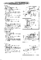
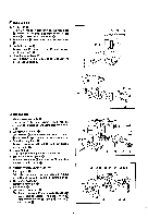
5. Raise the machine head. 6. Thread trimming arm B Insert it from above the bed. 7. Thread trimming arm A Fit the pin into the tip of connecting rod 0. slide thread trimming arm A onto the lower end of thread trimming arm B G. and snap stop ring ® on. 8. Needle plate assembly Fit the slot of thread trimming arm C over the pin on thread trimming arm B G. and tighten two ® each screws and CI. a) 9. Move movable knife until its tip meets the needle plate mark 0, and tighten screw 0. • - 0 • - El CLUTCH AND BRAKE I. Clutch lever assembly 0 0. Install clutch lever assembly 0 with washers 0. 0. 0. and bolt and hook one end of clutch spring 0 to spring hook 0. 2. Ball presser plate 0 Put steel bane in the ball holder. and temporarily 0 tighten it with two spring wahsers O and bolts 0. 3. Brake assembly 0 Fit it on the arm. and fasten with screw 0, making sure that the brake shoe is in line with the center of the stop cam. 4. Brake spring 0 Hook brake spring to the lower end of the brake assembly and the spring hook. • 0• 0 a • • 17 0 00 0 -14-
-
 1
1 -
2
-
3
-
4
-
5
-
6
-
7
-
8
-
9
-
10
-
 11
11 -
 12
12 -
 13
13 -
 14
14 -
 15
15 -
 16
16 -
 17
17 -
 18
18 -
 19
19 -
 20
20 -
 21
21 -
22
-
23
-
24
-
25
-
26
-
27
-
28
-
29
-
30
-
31
-
32
-
33
-
34
-
35
-
36
-
37
-
38
-
39
-
40
-
41
-
42
-
43
-
44
-
45
 |
 |
